Continue to Site

Welcome to EDAboard.com

Welcome to our site! EDAboard.com is an international Electronics Discussion Forum focused on EDA software, circuits, schematics, books, theory, papers, asic, pld, 8051, DSP, Network, RF, Analog Design, PCB, Service Manuals... and a whole lot more! To participate you need to register. Registration is free. Click here to register now.

pic16f877a MR TAHMID YOU PLEASE REPLAY

Status
Not open for further replies.

Drqadeer

Newbie level 4
Newbie level 4
Joined
May 1, 2013
Messages
5
Helped
0
Reputation
0
Reaction score
0
Trophy points
1,281
Visit site
Activity points
1,318
HELLO MR TAHMID,,, Ive read many posts and blogs by you and they are a lot of helpfull.
so i am going to define problem , if you read then please tell me in detail
i am going to use PIC16f877a, i want to use its analog inputs as analog inputs and Rc0 to Rc3 as digital input.... i am confsed on registers ADCON0 and ADCON1.....
what values i have to set to them..... using MIKROC 8.2 and 8Mhz crysal,,, also tell me which pf capicitors are better for 8Mhz , 12Mhz and 20Mhz
 

sorry I'm not Mr TAHMID. if my answer is valid use it otherwise ignore it.

also tell me which pf capicitors are better for 8Mhz , 12Mhz and 20Mhz
22pf will work fine for x-tals from 4MHz to 20MHz. (15pf to 33pf will work fine)


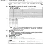
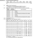
ADCON0=0X81;
ADCON1=0X84;

ADCON0
ADCON0.JPG

ADCON1
ADCON1.JPG

- - - Updated - - -

I read some of MR TAHMID posts. Really awesome especially abt his father and his guidance from school hood.
 
Last edited:
oh thanks a lot,,,,, i'll use it soon and replay you

- - - Updated - - -

i've checked values given by you on the datasheet registers, but it is quit different to my requirments...
i want to use all analog pins as analog and PORTC 0 to 3 PINS as Digital i/p.
TRISC=0x0f;
what about ADCON0 nd ADCON1
i think not
ADCON0=0x81;
ADOCON1=0x84;
 

Code:
TRISC=0x0f;    // 0f = 0000 1111   PORT C LSB 4 bits are digital I/P

Code:
ADCON0=0X81;
ADCON1=0X80;   // all AN pins are configured as Analog I/P pins. PCFG0 - PCFG3 are A/D port config bits

u need to select the analog channel before performing A/D conversion by changing CHS0 - CHS2 bits

u can use GO/DONE bit to perform A/D conversion.

- - - Updated - - -

accordingly set TRISA and TRISE as I/P.
 
Last edited:

thanks a lot, it works
i was taking analog voltage because i want to create veriable delay using VDelay function of mikroC , but it is not working
may be there is some problem in conversion.
so please some guidance about it, how to make a veriable delay using this analog input, say having 5V at input delay of 5s is required.
i was using some like that.
adc_rd=adc_read(2);
adc_rd=adc_rd/1023;
adc_rd=adc_rd*5000;
portb=oxff;
Vdelay(adc_rd);
portb=~portb;
Vdelay(adc_rd);
but it is not working, LEDs on portB are on for a long period (unknown period)
 

u can create ur own delay function using while or timer
so u can calculate the time easily based on the oscillator value (and setting like prescaler)
 

i cant understand.
any example
delay should veriable using an external veriable resistor on pic
 

simple delay using while loop

Code:
void delay(unsigned long);   // function init

void main()
{
delay(500); 
// or 
delay(i); 
// or
delay(AD_result);
// or
delay(AD_result*2);  
// or
delay(AD_result+5);

}

// delay function
void delay(unsigned long del_del)
{
	while(del_del--);
}
 

Status
Not open for further replies.

Similar threads

Part and Inventory Search

Welcome to EDABoard.com

Sponsor

Back
Top