Continue to Site

Welcome to EDAboard.com

Welcome to our site! EDAboard.com is an international Electronics Discussion Forum focused on EDA software, circuits, schematics, books, theory, papers, asic, pld, 8051, DSP, Network, RF, Analog Design, PCB, Service Manuals... and a whole lot more! To participate you need to register. Registration is free. Click here to register now.

PIC16F877A: cfgword2 not implemented (after changing from 8Mhz to 10MHz) @ UART com

Status
Not open for further replies.

cyb3rfreak

Newbie level 3
Joined
Feb 9, 2009
Messages
4
Helped
0
Reputation
0
Reaction score
0
Trophy points
1,281
Activity points
1,326
Hi All,


I recently simulate the diagram
uart.png no problems.png
using the actual components and no error/problems encountered at 8Mhz. But when I change the crystal at 10Mhz and settings on the PIC I got the problem on the Simulation Logs
problems.png

Btw, I use mikroC as programmer and proteus 8.1 as my simulator.

Any advice or suggestion will do...

Thanks.


Regards,
cyb3rfreak
 

We probably need to see the code (especially the part where you program the configuration registers) but I suspect that you have told the compiler that you are using a different chip. The PIC16F877A only has a single configuration register (which is why the simulator is complaining) but if you told the compiler/IDE that you are using some other device, then it will generate the HEX code for that device and its config register set.
Susan
 

Hi,


This are the code for the master (L) and slave (R):

Master:

Code C - [expand]
1
2
3
4
5
6
7
8
9
10
11
void main()
{
  TRISB = 0xFF; //PORTB as Input
  UART1_Init(9600); 
 
  do
  {
    UART1_Write(PORTB);
    delay_ms(100);
  }while(1);
}


Slave:

Code C - [expand]
1
2
3
4
5
6
7
8
9
10
11
12
13
void main()
{
   TRISB = 0x00; //PORTB as Output
   UART1_Init(9600);
 
   do
   {
      if(UART1_Data_Ready())       
        PORTB = UART1_Read();
     delay_ms(100);
 
   }while(1);
}


My purpose is to read the data from PORTB, then transmit it to the slave (R-MCU).
 
Last edited by a moderator:

As I said, we need to see "...especially the part where you program the config registers...".
You said the problem occurs when you change the crystal settings but that is not shown in the code you posted.
Susan
 

Hi,


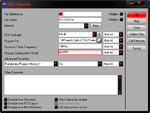
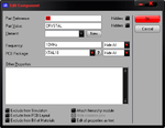
Those are all the codes from the circuit I obtained from the internet. As for the configuration, please see below:

Crystal:
crystal.png

MCU:
pic.png

MikroC (2MCUs)
mikroC_prgram.png mikroC_prgram-2.png

Thanks for the support.
 

The error report doesn't mention 16F877A, it says 168771. Either it is yet more wierdness in MikroC or you have the processor type set wrongly somewhere.

For a serial link, the only change necessary from moving from an 8MHz clock to a 10MHZ one is to use a new Baud rate divisor, assuming that is, that you want to keep the same link speed.

Brian.
 

Status
Not open for further replies.

Similar threads

Part and Inventory Search

Welcome to EDABoard.com

Sponsor

Back
Top