Continue to Site

Welcome to EDAboard.com

Welcome to our site! EDAboard.com is an international Electronics Discussion Forum focused on EDA software, circuits, schematics, books, theory, papers, asic, pld, 8051, DSP, Network, RF, Analog Design, PCB, Service Manuals... and a whole lot more! To participate you need to register. Registration is free. Click here to register now.

PIC16F877A and LCD pic c compiler(ccs) problem

Status
Not open for further replies.

pavelustinov

Newbie level 3
Joined
Mar 9, 2013
Messages
4
Helped
0
Reputation
0
Reaction score
0
Trophy points
1,281
Activity points
1,351
Hello everybody!
Can anyone help me to solve the problem?
I try to print a word on a LCD.
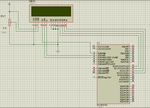
Program compiles successfully, but Proteus doesn't show anything.
Proteus just blink by the lights near LCD.
Proteus scheme listed below.
I think, it just connection problem.

main.h

Code C - [expand]
1
2
3
4
5
6
7
8
9
10
11
12
13
14
#include <16F877A.h>
#device adc=8
 
#FUSES NOWDT                    //No Watch Dog Timer
#FUSES RC                       //Resistor/Capacitor Osc with CLKOUT
#FUSES NOPUT                    //No Power Up Timer
#FUSES NOPROTECT                //Code not protected from reading
#FUSES NODEBUG                  //No Debug mode for ICD
#FUSES BROWNOUT                 //Reset when brownout detected
#FUSES NOLVP                    //No low voltage prgming, B3(PIC16) or B5(PIC18) used for I/O
#FUSES NOCPD                    //No EE protection
#FUSES NOWRT                    //Program memory not write protected
 
#use delay(clock=20000000)


main.c

Code C - [expand]
1
2
3
4
5
6
7
8
9
10
11
12
13
14
15
16
17
18
19
20
21
22
23
#include "main.h"
 
#include <flex_lcd.c>
 
void main()
{
   lcd_init();
   
   setup_adc_ports(NO_ANALOGS);
   setup_adc(ADC_OFF);
   setup_psp(PSP_DISABLED);
   setup_spi(SPI_SS_DISABLED);
   setup_timer_0(RTCC_INTERNAL|RTCC_DIV_1);
   setup_timer_1(T1_DISABLED);
   setup_timer_2(T2_DISABLED,0,1);
   setup_comparator(NC_NC_NC_NC);
   setup_vref(FALSE);
   
   while(1) {
      lcd_putc("\fReady...\n");
      delay_ms(700);
   }
}


flex_lcd.c

Code C - [expand]
1
2
3
4
5
6
7
8
9
10
11
12
13
14
15
16
17
18
19
20
21
22
23
24
25
26
27
28
29
30
31
32
33
34
35
36
37
38
39
40
41
42
43
44
45
46
47
48
49
50
51
52
53
54
55
56
57
58
59
60
61
62
63
64
65
66
67
68
69
70
71
72
73
74
75
76
77
78
79
80
81
82
83
84
85
86
87
88
89
90
91
92
93
94
95
96
97
98
99
100
101
102
103
104
105
106
107
108
109
110
111
112
113
114
115
116
117
118
119
120
121
122
123
124
125
126
127
128
129
130
131
132
133
134
135
136
137
138
139
140
141
142
143
144
145
146
147
148
149
150
151
152
153
154
155
156
157
158
159
160
161
162
163
164
165
166
167
168
169
170
171
172
173
174
175
176
177
178
179
180
181
182
183
184
185
186
187
188
189
190
191
192
193
194
195
196
197
198
199
200
201
202
203
204
205
206
207
208
209
210
211
212
213
214
215
216
217
218
219
220
221
222
223
224
225
226
227
228
229
230
231
232
// flex_lcd.c 
 
 // These pins are for the Microchip PicDem2-Plus board, 
 // which is what I used to test the driver.  Change these 
 // pins to fit your own board. 
 
 #define LCD_DB4   PIN_C0 
 #define LCD_DB5   PIN_C1 
 #define LCD_DB6   PIN_C2 
 #define LCD_DB7   PIN_C3 
 
 #define LCD_E     PIN_A1 
 #define LCD_RS    PIN_A0 
 #define LCD_RW    PIN_A2 
 
 // If you only want a 6-pin interface to your LCD, then 
 // connect the R/W pin on the LCD to ground, and comment 
 // out the following line. 
 
// #define USE_LCD_RW   1      
 
 //======================================== 
 
 #define lcd_type 2        // 0=5x7, 1=5x10, 2=2 lines 
 #define lcd_line_two 0x40 // LCD RAM address for the 2nd line 
 
 
 int8 const LCD_INIT_STRING[4] = 
 { 
  0x20 | (lcd_type << 2), // Func set: 4-bit, 2 lines, 5x8 dots 
  0xc,                    // Display on 
  1,                      // Clear display 
  6                       // Increment cursor 
  }; 
                               
 
 //------------------------------------- 
 void lcd_send_nibble(int8 nibble) 
 { 
 // Note:  !! converts an integer expression 
 // to a boolean (1 or 0). 
  output_bit(LCD_DB4, !!(nibble & 1)); 
  output_bit(LCD_DB5, !!(nibble & 2));  
  output_bit(LCD_DB6, !!(nibble & 4));    
  output_bit(LCD_DB7, !!(nibble & 8));    
 
  delay_cycles(1); 
  output_high(LCD_E); 
  delay_us(2); 
  output_low(LCD_E); 
 } 
 
 //----------------------------------- 
 // This sub-routine is only called by lcd_read_byte(). 
 // It's not a stand-alone routine.  For example, the 
 // R/W signal is set high by lcd_read_byte() before 
 // this routine is called.      
 
 #ifdef USE_LCD_RW 
 int8 lcd_read_nibble(void) 
 { 
 int8 retval; 
 // Create bit variables so that we can easily set 
 // individual bits in the retval variable. 
 #bit retval_0 = retval.0 
 #bit retval_1 = retval.1 
 #bit retval_2 = retval.2 
 #bit retval_3 = retval.3 
 
 retval = 0; 
     
 output_high(LCD_E); 
 delay_cycles(1); 
 
 retval_0 = input(LCD_DB4); 
 retval_1 = input(LCD_DB5); 
 retval_2 = input(LCD_DB6); 
 retval_3 = input(LCD_DB7); 
   
 output_low(LCD_E); 
     
 return(retval);    
 }    
 #endif 
 
 //--------------------------------------- 
 // Read a byte from the LCD and return it. 
 
 #ifdef USE_LCD_RW 
 int8 lcd_read_byte(void) 
 { 
 int8 low; 
 int8 high; 
 
 output_high(LCD_RW); 
 delay_cycles(1); 
 
 high = lcd_read_nibble(); 
 
 low = lcd_read_nibble(); 
 
 return( (high<<4) | low); 
 } 
 #endif 
 
 //---------------------------------------- 
 // Send a byte to the LCD. 
 void lcd_send_byte(int8 address, int8 n) 
 { 
 output_low(LCD_RS); 
 
 #ifdef USE_LCD_RW 
 while(bit_test(lcd_read_byte(),7)) ; 
 #else 
 delay_us(60);  
 #endif 
 
 if(address) 
    output_high(LCD_RS); 
 else 
    output_low(LCD_RS); 
       
  delay_cycles(1); 
 
 #ifdef USE_LCD_RW 
 output_low(LCD_RW); 
 delay_cycles(1); 
 #endif 
 
 output_low(LCD_E); 
 
 lcd_send_nibble(n >> 4); 
 lcd_send_nibble(n & 0xf); 
 } 
 
 //---------------------------- 
 void lcd_init(void) 
 { 
 int8 i; 
 
 output_low(LCD_RS); 
 
 #ifdef USE_LCD_RW 
 output_low(LCD_RW); 
 #endif 
 
 output_low(LCD_E); 
 
 delay_ms(15); 
 
 for(i=0 ;i < 3; i++) 
    { 
     lcd_send_nibble(0x03); 
     delay_ms(5); 
    } 
 
 lcd_send_nibble(0x02); 
 
 for(i=0; i < sizeof(LCD_INIT_STRING); i++) 
    { 
     lcd_send_byte(0, LCD_INIT_STRING[i]); 
     
     // If the R/W signal is not used, then 
     // the busy bit can't be polled.  One of 
     // the init commands takes longer than 
     // the hard-coded delay of 60 us, so in 
     // that case, lets just do a 5 ms delay 
     // after all four of them. 
     #ifndef USE_LCD_RW 
     delay_ms(5); 
     #endif 
    } 
 
 } 
 
 //---------------------------- 
 
 void lcd_gotoxy(int8 x, int8 y) 
 { 
 int8 address; 
 
 if(y != 1) 
    address = lcd_line_two; 
 else 
    address=0; 
 
 address += x-1; 
 lcd_send_byte(0, 0x80 | address); 
 } 
 
 //----------------------------- 
 void lcd_putc(char c) 
 { 
  switch(c) 
    { 
     case '\f': 
       lcd_send_byte(0,1); 
       delay_ms(2); 
       break; 
     
     case '\n': 
        lcd_gotoxy(1,2); 
        break; 
     
     case '\b': 
        lcd_send_byte(0,0x10); 
        break; 
     
     default: 
        lcd_send_byte(1,c); 
        break; 
    } 
 } 
 
 //------------------------------ 
 #ifdef USE_LCD_RW 
 char lcd_getc(int8 x, int8 y) 
 { 
 char value; 
 
 lcd_gotoxy(x,y); 
 
 // Wait until busy flag is low. 
 while(bit_test(lcd_read_byte(),7));  
 
 output_high(LCD_RS); 
 value = lcd_read_byte(); 
 output_low(lcd_RS); 
 
 return(value); 
 } 
 #endif


proteus.png
 

You have to define LCD pins in main.c. You are using PORTA for LCD and it has ADC function. have you set the PORTA as digital output port?

Ok. Just pullup MCLR pin i.e., connect a 10 k resistor between MCLR pin and +5V. It will work.
 

You have to define LCD pins in main.c. You are using PORTA for LCD and it has ADC function. have you set the PORTA as digital output port?

Ok. Just pullup MCLR pin i.e., connect a 10 k resistor between MCLR pin and +5V. It will work.

Solved!
I connect 5 pin LCD to ground and it work's!!!
One more question. I know it's stupid question.

One word I can display by
lcd_putc("\fReady...");
But if I write
int j;
j = 1212;
lcd_putc(j);
LCD shows something strange.


Code C - [expand]
1
2
3
4
5
6
7
8
9
10
11
12
13
14
15
16
17
18
19
20
21
unsigned char myString[5];
unsigned int myInt = 0;
 
void main {
 
    myInt = 5432;
 
    while(1) {
 
 
        myString[0] = myInt/1000 + 0x30;
        myString[1] = (myInt/100)%10 + 0x30;
        myString[2] = (myInt/10)%10 + 0x30;
        myString[3] = (myInt/1)%10 + 0x30;
        myString[4] = '\0';


    }
 
}

 
Last edited:

There a "lapse" in code!!!

unsigned int myStr = 0; is unsigned int myInt = 0;???

And Display show 0056 in my case (not 5432)!!!

Code:
#include <16C76.h>
#device adc=8

#FUSES NOWDT                    //No Watch Dog Timer
#FUSES HS                       //High speed Osc (> 4mhz for PCM/PCH) (>10mhz for PCD)
#FUSES NOBROWNOUT               //No brownout reset

#use delay(clock=16000000)

#define LCD_DATA_PORT getenv("SFR:PORTC")
#include <lcd.c>

#define LED_OSC      PIN_A5

unsigned char myString[5];
unsigned int myInt = 0;

void main()
{
   set_tris_a(0x00);
   set_tris_b(0x00);
   set_tris_c(0x00);
   lcd_init();   
  
   while(TRUE)
   {
      OUTPUT_TOGGLE(LED_OSC);
      myInt = 5432;
      delay_ms(10);
      printf (lcd_putc,"\f\%d\n",myInt);
      myString[0] = myInt/1000 + 0x30;
      myString[1] = (myInt/100)%10 + 0x30;
      myString[2] = (myInt/10)%10 + 0x30;
      myString[3] = (myInt/1)%10 + 0x30;
      myString[4] = '\0';      
      printf (lcd_putc,myString);
      //myInt++;
   }
}

LCD.C
Code:
///////////////////////////////////////////////////////////////////////////////
////                             LCD.C                                     ////
////                 Driver for common LCD modules                         ////
////                                                                       ////
////  lcd_init()   Must be called before any other function.               ////
////                                                                       ////
////  lcd_putc(c)  Will display c on the next position of the LCD.         ////
////                 \a  Set cursor position to upper left                 ////
////                 \f  Clear display, set cursor to upper left           ////
////                 \n  Go to start of second line                        ////
////                 \b  Move back one position                            ////
////              If LCD_EXTENDED_NEWLINE is defined, the \n character     ////
////              will erase all remanining characters on the current      ////
////              line, and move the cursor to the beginning of the next   ////
////              line.                                                    ////
////              If LCD_EXTENDED_NEWLINE is defined, the \r character     ////
////              will move the cursor to the start of the current         ////
////              line.                                                    ////
////                                                                       ////
////  lcd_gotoxy(x,y) Set write position on LCD (upper left is 1,1)        ////
////                                                                       ////
////  lcd_getc(x,y)   Returns character at position x,y on LCD             ////
////                                                                       ////
////  lcd_cursor_on(int1 on)   Turn the cursor on (on=TRUE) or off         ////
////              (on=FALSE).                                              ////
////                                                                       ////
////  lcd_set_cgram_char(w, *p)   Write a custom character to the CGRAM.   ////
////                                                                       ////
////                                                                       ////
////  CONFIGURATION                                                        ////
////  The LCD can be configured in one of two ways: a.) port access or     ////
////  b.) pin access.  Port access requires the entire 7 bit interface     ////
////  connected to one GPIO port, and the data bits (D4:D7 of the LCD)     ////
////  connected to sequential pins on the GPIO.  Pin access                ////
////  has no requirements, all 7 bits of the control interface can         ////
////  can be connected to any GPIO using several ports.                    ////
////                                                                       ////
////  To use port access, #define LCD_DATA_PORT to the SFR location of     ////
////  of the GPIO port that holds the interface, -AND- edit LCD_PIN_MAP    ////
////  of this file to configure the pin order.  If you are using a         ////
////  baseline PIC (PCB), then LCD_OUTPUT_MAP and LCD_INPUT_MAP also must  ////
////  be defined.                                                          ////
////                                                                       ////
////  Example of port access:                                              ////
////     #define LCD_DATA_PORT getenv("SFR:PORTD")                         ////
////                                                                       ////
////  To use pin access, the following pins must be defined:               ////
////     LCD_ENABLE_PIN                                                    ////
////     LCD_RS_PIN                                                        ////
////     LCD_RW_PIN                                                        ////
////     LCD_DATA4                                                         ////
////     LCD_DATA5                                                         ////
////     LCD_DATA6                                                         ////
////     LCD_DATA7                                                         ////
////                                                                       ////
////  Example of pin access:                                               ////
////     #define LCD_ENABLE_PIN  PIN_E0                                    ////
////     #define LCD_RS_PIN      PIN_E1                                    ////
////     #define LCD_RW_PIN      PIN_E2                                    ////
////     #define LCD_DATA4       PIN_D4                                    ////
////     #define LCD_DATA5       PIN_D5                                    ////
////     #define LCD_DATA6       PIN_D6                                    ////
////     #define LCD_DATA7       PIN_D7                                    ////
////                                                                       ////
///////////////////////////////////////////////////////////////////////////////
////        (C) Copyright 1996,2010 Custom Computer Services           ////
//// This source code may only be used by licensed users of the CCS C  ////
//// compiler.  This source code may only be distributed to other      ////
//// licensed users of the CCS C compiler.  No other use, reproduction ////
//// or distribution is permitted without written permission.          ////
//// Derivative programs created using this software in object code    ////
//// form are not restricted in any way.                               ////
///////////////////////////////////////////////////////////////////////////

#ifndef __LCD_C__
#define __LCD_C__

// define the pinout.
// only required if port access is being used.
typedef struct  
{                            // This structure is overlayed
   int1 enable;           // on to an I/O port to gain
   int1 rs;               // access to the LCD pins.
   int1 rw;               // The bits are allocated from
   int1 unused;           // low order up.  ENABLE will
   unsigned int     data : 4;         // be LSB pin of that port.
  #if defined(__PCD__)       // The port used will be LCD_DATA_PORT.
   unsigned int    reserved: 8;
  #endif
} LCD_PIN_MAP;

// this is to improve compatability with previous LCD drivers that accepted
// a define labeled 'use_portb_lcd' that configured the LCD onto port B.
#if ((defined(use_portb_lcd)) && (use_portb_lcd==TRUE))
 #define LCD_DATA_PORT getenv("SFR:PORTB")
#endif

#if defined(__PCB__)
   // these definitions only need to be modified for baseline PICs.
   // all other PICs use LCD_PIN_MAP or individual LCD_xxx pin definitions.
/*                                    EN, RS,   RW,   UNUSED,  DATA  */
 const LCD_PIN_MAP LCD_OUTPUT_MAP =  {0,  0,    0,    0,       0};
 const LCD_PIN_MAP LCD_INPUT_MAP =   {0,  0,    0,    0,       0xF};
#endif

////////////////////// END CONFIGURATION ///////////////////////////////////

#ifndef LCD_ENABLE_PIN
   #define lcd_output_enable(x) lcdlat.enable=x
   #define lcd_enable_tris()   lcdtris.enable=0
#else
   #define lcd_output_enable(x) output_bit(LCD_ENABLE_PIN, x)
   #define lcd_enable_tris()  output_drive(LCD_ENABLE_PIN)
#endif

#ifndef LCD_RS_PIN
   #define lcd_output_rs(x) lcdlat.rs=x
   #define lcd_rs_tris()   lcdtris.rs=0
#else
   #define lcd_output_rs(x) output_bit(LCD_RS_PIN, x)
   #define lcd_rs_tris()  output_drive(LCD_RS_PIN)
#endif

#ifndef LCD_RW_PIN
   #define lcd_output_rw(x) lcdlat.rw=x
   #define lcd_rw_tris()   lcdtris.rw=0
#else
   #define lcd_output_rw(x) output_bit(LCD_RW_PIN, x)
   #define lcd_rw_tris()  output_drive(LCD_RW_PIN)
#endif

// original version of this library incorrectly labeled LCD_DATA0 as LCD_DATA4,
// LCD_DATA1 as LCD_DATA5, and so on.  this block of code makes the driver
// compatible with any code written for the original library
#if (defined(LCD_DATA0) && defined(LCD_DATA1) && defined(LCD_DATA2) && defined(LCD_DATA3) && !defined(LCD_DATA4) && !defined(LCD_DATA5) && !defined(LCD_DATA6) && !defined(LCD_DATA7))
   #define  LCD_DATA4    LCD_DATA0
   #define  LCD_DATA5    LCD_DATA1
   #define  LCD_DATA6    LCD_DATA2
   #define  LCD_DATA7    LCD_DATA3
#endif

#ifndef LCD_DATA4
#ifndef LCD_DATA_PORT
   #if defined(__PCB__)
      #define LCD_DATA_PORT      0x06     //portb
      #define set_tris_lcd(x)   set_tris_b(x)
   #else
     #if defined(PIN_D0)
      #define LCD_DATA_PORT      getenv("SFR:PORTD")     //portd
     #else
      #define LCD_DATA_PORT      getenv("SFR:PORTB")     //portb
     #endif
   #endif   
#endif

#if defined(__PCB__)
   LCD_PIN_MAP lcd, lcdlat;
   #byte lcd = LCD_DATA_PORT
   #byte lcdlat = LCD_DATA_PORT
#elif defined(__PCM__)
   LCD_PIN_MAP lcd, lcdlat, lcdtris;
   #byte lcd = LCD_DATA_PORT
   #byte lcdlat = LCD_DATA_PORT
   #byte lcdtris = LCD_DATA_PORT+0x80
#elif defined(__PCH__)
   LCD_PIN_MAP lcd, lcdlat, lcdtris;
   #byte lcd = LCD_DATA_PORT
   #byte lcdlat = LCD_DATA_PORT+9
   #byte lcdtris = LCD_DATA_PORT+0x12
#elif defined(__PCD__)
   LCD_PIN_MAP lcd, lcdlat, lcdtris;
   #word lcd = LCD_DATA_PORT
   #word lcdlat = LCD_DATA_PORT+2
   #word lcdtris = LCD_DATA_PORT-0x02
#endif
#endif   //LCD_DATA4 not defined

#ifndef LCD_TYPE
   #define LCD_TYPE 2           // 0=5x7, 1=5x10, 2=2 lines
#endif

#ifndef LCD_LINE_TWO
   #define LCD_LINE_TWO 0x40    // LCD RAM address for the second line
#endif

#ifndef LCD_LINE_LENGTH
   #define LCD_LINE_LENGTH 20
#endif

unsigned int8 const LCD_INIT_STRING[4] = {0x20 | (LCD_TYPE << 2), 0xc, 1, 6};
                             // These bytes need to be sent to the LCD
                             // to start it up.

unsigned int8 lcd_read_nibble(void);

unsigned int8 lcd_read_byte(void)
{
   unsigned int8 low,high;

 #if defined(__PCB__)
   set_tris_lcd(LCD_INPUT_MAP);
 #else
  #if (defined(LCD_DATA4) && defined(LCD_DATA5) && defined(LCD_DATA6) && defined(LCD_DATA7))
   output_float(LCD_DATA4);
   output_float(LCD_DATA5);
   output_float(LCD_DATA6);
   output_float(LCD_DATA7);
  #else
   lcdtris.data = 0xF;
  #endif
 #endif
        
   lcd_output_rw(1);
   delay_cycles(1);
   lcd_output_enable(1);
   delay_cycles(1);
   high = lcd_read_nibble();
      
   lcd_output_enable(0);
   delay_cycles(1);
   lcd_output_enable(1);
   delay_us(1);
   low = lcd_read_nibble();
      
   lcd_output_enable(0);

 #if defined(__PCB__)
   set_tris_lcd(LCD_OUTPUT_MAP);
 #else
  #if (defined(LCD_DATA4) && defined(LCD_DATA5) && defined(LCD_DATA6) && defined(LCD_DATA7))
   output_drive(LCD_DATA4);
   output_drive(LCD_DATA5);
   output_drive(LCD_DATA6);
   output_drive(LCD_DATA7);
  #else
   lcdtris.data = 0x0;
  #endif
 #endif

   return( (high<<4) | low);
}

unsigned int8 lcd_read_nibble(void)
{
  #if (defined(LCD_DATA4) && defined(LCD_DATA5) && defined(LCD_DATA6) && defined(LCD_DATA7))
   unsigned int8 n = 0x00;

   /* Read the data port */
   n |= input(LCD_DATA4);
   n |= input(LCD_DATA5) << 1;
   n |= input(LCD_DATA6) << 2;
   n |= input(LCD_DATA7) << 3;
   
   return(n);
  #else
   return(lcd.data);
  #endif
}

void lcd_send_nibble(unsigned int8 n)
{
  #if (defined(LCD_DATA4) && defined(LCD_DATA5) && defined(LCD_DATA6) && defined(LCD_DATA7))
   /* Write to the data port */
   output_bit(LCD_DATA4, bit_test(n, 0));
   output_bit(LCD_DATA5, bit_test(n, 1));
   output_bit(LCD_DATA6, bit_test(n, 2));
   output_bit(LCD_DATA7, bit_test(n, 3));
  #else      
   lcdlat.data = n;
  #endif
      
   delay_cycles(1);
   lcd_output_enable(1);
   delay_us(2);
   lcd_output_enable(0);
}

void lcd_send_byte(unsigned int8 address, unsigned int8 n)
{
  #if defined(__PCB__)
   set_tris_lcd(LCD_OUTPUT_MAP);
  #else
   lcd_enable_tris();
   lcd_rs_tris();
   lcd_rw_tris();
  #endif

   lcd_output_rs(0);
   while ( bit_test(lcd_read_byte(),7) ) ;
   lcd_output_rs(address);
   delay_cycles(1);
   lcd_output_rw(0);
   delay_cycles(1);
   lcd_output_enable(0);
   lcd_send_nibble(n >> 4);
   lcd_send_nibble(n & 0xf);
}

#if defined(LCD_EXTENDED_NEWLINE)
unsigned int8 g_LcdX, g_LcdY;
#endif

void lcd_init(void) 
{
   unsigned int8 i;

 #if defined(__PCB__)
   set_tris_lcd(LCD_OUTPUT_MAP);
 #else
  #if (defined(LCD_DATA4) && defined(LCD_DATA5) && defined(LCD_DATA6) && defined(LCD_DATA7))
   output_drive(LCD_DATA4);
   output_drive(LCD_DATA5);
   output_drive(LCD_DATA6);
   output_drive(LCD_DATA7);
  #else
   lcdtris.data = 0x0;
  #endif
   lcd_enable_tris();
   lcd_rs_tris();
   lcd_rw_tris();
 #endif

   lcd_output_rs(0);
   lcd_output_rw(0);
   lcd_output_enable(0);
    
   delay_ms(15);
   for(i=1;i<=3;++i)
   {
       lcd_send_nibble(3);
       delay_ms(5);
   }
   
   lcd_send_nibble(2);
   delay_ms(5);
   for(i=0;i<=3;++i)
      lcd_send_byte(0,LCD_INIT_STRING[i]);

  #if defined(LCD_EXTENDED_NEWLINE)
   g_LcdX = 0;
   g_LcdY = 0;
  #endif
}

void lcd_gotoxy(unsigned int8 x, unsigned int8 y)
{
   unsigned int8 address;
   
   if(y!=1)
      address=LCD_LINE_TWO;
   else
      address=0;
     
   address+=x-1;
   lcd_send_byte(0,0x80|address);

  #if defined(LCD_EXTENDED_NEWLINE)
   g_LcdX = x - 1;
   g_LcdY = y - 1;
  #endif
}

void lcd_putc(char c)
{
   switch (c)
   {
      case '\a'   :  lcd_gotoxy(1,1);     break;

      case '\f'   :  lcd_send_byte(0,1);
                     delay_ms(2);
                    #if defined(LCD_EXTENDED_NEWLINE)
                     g_LcdX = 0;
                     g_LcdY = 0;
                    #endif
                     break;

     #if defined(LCD_EXTENDED_NEWLINE)
      case '\r'   :  lcd_gotoxy(1, g_LcdY+1);   break;
      case '\n'   :
         while (g_LcdX++ < LCD_LINE_LENGTH)
         {
            lcd_send_byte(1, ' ');
         }
         lcd_gotoxy(1, g_LcdY+2);
         break;
     #else
      case '\n'   : lcd_gotoxy(1,2);        break;
     #endif
     
      case '\b'   : lcd_send_byte(0,0x10);  break;
     
     #if defined(LCD_EXTENDED_NEWLINE)
      default     : 
         if (g_LcdX < LCD_LINE_LENGTH)
         {
            lcd_send_byte(1, c);
            g_LcdX++;
         }
         break;
     #else
      default     : lcd_send_byte(1,c);     break;
     #endif
   }
}
 
char lcd_getc(unsigned int8 x, unsigned int8 y)
{
   char value;

   lcd_gotoxy(x,y);
   while ( bit_test(lcd_read_byte(),7) ); // wait until busy flag is low
   lcd_output_rs(1);
   value = lcd_read_byte();
   lcd_output_rs(0);
   
   return(value);
}

// write a custom character to the ram
// which is 0-7 and specifies which character array we are modifying.
// ptr points to an array of 8 bytes, where each byte is the next row of
//    pixels.  only bits 0-4 are used.  the last row is the cursor row, and
//    usually you will want to leave this byte 0x00.
void lcd_set_cgram_char(unsigned int8 which, unsigned int8 *ptr)
{
   unsigned int i;

   which <<= 3;
   which &= 0x38;

   lcd_send_byte(0, 0x40 | which);  //set cgram address

   for(i=0; i<8; i++)
   {
      lcd_send_byte(1, *ptr++);
   }
  
   #if defined(LCD_EXTENDED_NEWLINE)
    lcd_gotoxy(g_LcdX+1, g_LcdY+1);  //set ddram address
   #endif
}

void lcd_cursor_on(int1 on)
{
   if (on)
   {
      lcd_send_byte(0,0x0F);           //turn LCD cursor ON
   }
   else
   {
      lcd_send_byte(0,0x0C);           //turn LCD cursor OFF
   }
}

#endif

Using attached flex_lcd.c have a same result!!!

Or using too

Code:
char buffer[5];
...
      sprintf(buffer, "\%05d", myInt);
      printf (lcd_putc,buffer);

Thanks
 
Last edited:
Status
Not open for further replies.

Similar threads

Part and Inventory Search

Welcome to EDABoard.com

Sponsor

Back
Top