pic.programmer
Advanced Member level 3
Hi
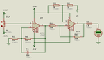
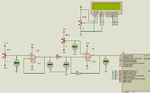
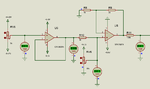
I am making a pH meter. I have built the pH probe interfacing circuit and it is working fine. Now I need some help in ADC voltage to pH conversion.
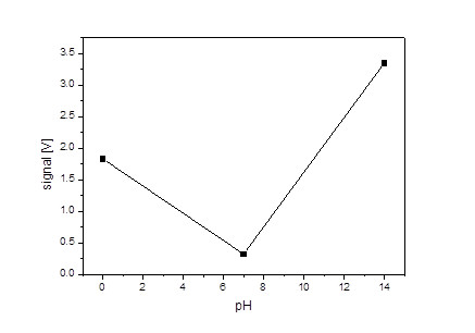
pH range is 0 to 14.
voltages are like this.
0-2.5633 V
7-2.985 V
14-2.137 V
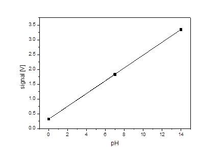
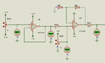
How to convert these voltages to 0 to 14 values. Also I need to convert the voltages like this.
2.5633 - 2.985 to 0 to +420mV
2.5633 - 2.137 to 0 to -420 mV.
How to do these conversions.
I am making a pH meter. I have built the pH probe interfacing circuit and it is working fine. Now I need some help in ADC voltage to pH conversion.
pH range is 0 to 14.
voltages are like this.
0-2.5633 V
7-2.985 V
14-2.137 V
How to convert these voltages to 0 to 14 values. Also I need to convert the voltages like this.
2.5633 - 2.985 to 0 to +420mV
2.5633 - 2.137 to 0 to -420 mV.
How to do these conversions.
")