Continue to Site

Welcome to EDAboard.com

Welcome to our site! EDAboard.com is an international Electronics Discussion Forum focused on EDA software, circuits, schematics, books, theory, papers, asic, pld, 8051, DSP, Network, RF, Analog Design, PCB, Service Manuals... and a whole lot more! To participate you need to register. Registration is free. Click here to register now.

pic multiplexing doubt

Status
Not open for further replies.

zeroskj1988

Member level 2
Joined
Jul 7, 2011
Messages
46
Helped
1
Reputation
2
Reaction score
1
Trophy points
1,288
Activity points
1,588
hello sir,
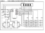
i have circuit from microchip pic micro controller.i am posting that circuit here.i need to clarify one doubt,when i saw this circuit.there is portion of circuit where 7 segment sinking transistor and analog signal is multiplexed.my doubt is in this particular circuit,when analog signal approaches 5/4v,is there any chance of turning on that transistor,without pic's output goes high.
and also whether this circuit will work well with the pic16f877a
thank you in advance untitled.JPG
 

Hi;
This is an old but interesting demo from Microchip (appnote 557), demonstrating how to use
a low pin PIC for a complex task.

-- is there any chance of turning on that transistor,without pic's output goes high ...
Yes, of course, there's a chance :) - ) but it does not matter because during the AD measuring
the PORTB is disabled via the software. See the source (MPLXAD.ASM).
But because of the voltage dividing (in this case it's also nonlinear) always use analog buffer!

-- and also whether this circuit will work well with the pic16f877a ...
Yes, it will work, with the appropriate conversion of the software :) - ).
However, the 16f877a has much more IO pins so you can prevent using
a pin as analog-digital IO (for example).
 
thank you for the reply.i have one doubt left.if the transistor turned on then is there any chance for the discharge of 10uf capacitor.in my application the charge of that capacitor is of particular importance,that is why i am repeating.sorry for any mistakes
 

Ya it should work,When I did it I used BC547 as the transistor,10K for the base resistor,for the data resistor I used 330 ohms rather 220 ohms,but that also depends on the Seven Segment Display type I used FND506 common cathode but any general common cathode of rating, 25mA of If (forward current per segment) and peak forward current of 200mA with Vf forward voltage drop of 1.5 to 2 volt should work.

But the main stuff is about multiplexing,in software you should provide enough time for each display to be illuminated approx 5ms to 20ms the more enable time each display gets the more bright your display will be.

Good Luck
 

Yes, if the transistor turned on via the PORTA digital output pin, it also charges the 10 nF
(and NOT 10 uF !) to 5 V, and if it's turned off, the cap is discharged, ie goes to 0 V.

Did you find my above answers helpful? Click! :) - )
 
Status
Not open for further replies.

Similar threads

Part and Inventory Search

Welcome to EDABoard.com

Sponsor

Back
Top