Continue to Site

Welcome to EDAboard.com

Welcome to our site! EDAboard.com is an international Electronics Discussion Forum focused on EDA software, circuits, schematics, books, theory, papers, asic, pld, 8051, DSP, Network, RF, Analog Design, PCB, Service Manuals... and a whole lot more! To participate you need to register. Registration is free. Click here to register now.

PIC + 555, variable square wave pulse for tachometer

Status
Not open for further replies.

shsn

Junior Member level 3
Joined
Nov 28, 2012
Messages
26
Helped
0
Reputation
0
Reaction score
0
Trophy points
1,281
Activity points
1,523
I've done some readings on how tachometers (as in automobile tachometers used to measure engine RPM) works. Apparently modern tachometers drive the needle from the signal received from its signal wire; which is a series of square wave pulses. If I'm not mistaken the frequency determines what RPM the engine is running. So as a holiday project I want to build a circuit/design that uses PIC (USB-compatible so it can be connected to a computer) to operate a tachometer.

It seems the best way to get started is using 555 timer to generate the required square wave signal. But I do not know how to 'vary' the frequency of 555 timer using a PIC, is this even possible? or can a specific model of PIC can do all these all in one?

Regards.
 

There is really no need to incorporate a 555 timer into the design.

Most microcontrollers, including PICs, can easily generate a pulse train or PWM and most tachometer designs do not require such signal to be an effective design.

Typically tachometer designs utilize an IR sensor coupled by an IR source with the signal from the sensor fed to Timer operating in Capture Mode.

Take a look at the CCP module in your PICs datasheet.

The following are examples of PIC based simple tachometer designs:

RevMaster - A Simple Tachometer


Build A Digital Tachometer/RPM Counter

DIY PIC Microcontroller Based Digital Tachometer Project

BigDog
 

Hi BigDog, thanks for the reply.

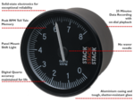
Yes, measuring using the sensor seems not so difficult. But what I meant was that I need to drive one of these,
product_graphic_ST400.png

These electronic tachometers have a signal wire that requires square wave pulses.
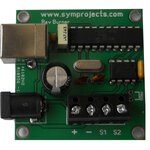
But these guys seemed to achieved this using a PIC and some sort of 555 timer (I'm not so sure what it is, can't read the markings) like this,
rev2.jpg

Cheers.
 

The bottom photo is not of a tachometer, it is a RPM simulator used to drive a tachometer by simulating the pulses from the ignition coil or electronic ignition module.

The small IC you are referring to is certainly a level shifter or transceiver, not a 555 timer, as most automotive tachometers require/expect a 12V level signal from the ignition coil or electronic ignition electronic ignition module.

As I've previously indicated many PIC offer a separate peripheral module whose purpose is to generate a pulse train or PWM signal output.

PICs without this module can also effectively generate a pulse train or PWM signal by means of a software implementation.

However, in both cases the level of the simulated output signal, in this case 5v from USB supply, must be raised or level shifted to the 12v required by an automotive tachometer.

Rev Burner Installation Instructions:

The 12V wire: usually its colour is RED and carries a 12V voltage to power the rev counter. It does not power the light of the rev counter though.
In a real car it would be connected to the ignition switch but we connect it to the + terminal of the board (see photo).
The type of signal generated by the Rev Burner is a square wave at 12V, whose frequency increases with the speed.
The Rev Burner is able to generate up to 67,164 pulses per minute and most of the electronic speedometers work or can be set to work in this range of frequency.

The ground wire: it is BLACK and it should be connected to the battery ground. We connect it to the terminal with the – (see photo).

The coil wire is usually BLUE and should be connected to the ignition coil. This wire carries the information about the engine rotation speed.
Must be connected to the S1 terminal (see picture).

Terminal S2 on the Rev Burner’s PCB is not used at the moment.


The analog gauge in the first photo is an automotive tachometer:

ST400 Series TACHOMETERS User Manual


The Rev Burner appears to be using a PIC18 series device, there are several which offer a USB peripheral module:

Microchip PIC18 Parametric Search

Click the radio button Show All Specs, select Full Speed under USB Speed and enter SPDIP under Packages.

One commonly used versions in an SPDIP package, the same used in the Rev Burner, is the PIC18F2550.


After closer examination of the second photo, they appear to be using a PIC18F14K50.


BigDog
 

Status
Not open for further replies.

Part and Inventory Search

Welcome to EDABoard.com

Sponsor

Back
Top