Continue to Site

Welcome to EDAboard.com

Welcome to our site! EDAboard.com is an international Electronics Discussion Forum focused on EDA software, circuits, schematics, books, theory, papers, asic, pld, 8051, DSP, Network, RF, Analog Design, PCB, Service Manuals... and a whole lot more! To participate you need to register. Registration is free. Click here to register now.

[SOLVED] PIC 18F452 ,LM35 input unstable

Status
Not open for further replies.

cheetha

Full Member level 2
Joined
Sep 17, 2011
Messages
146
Helped
1
Reputation
2
Reaction score
2
Trophy points
1,298
Activity points
2,310
Assalam-o-alekum

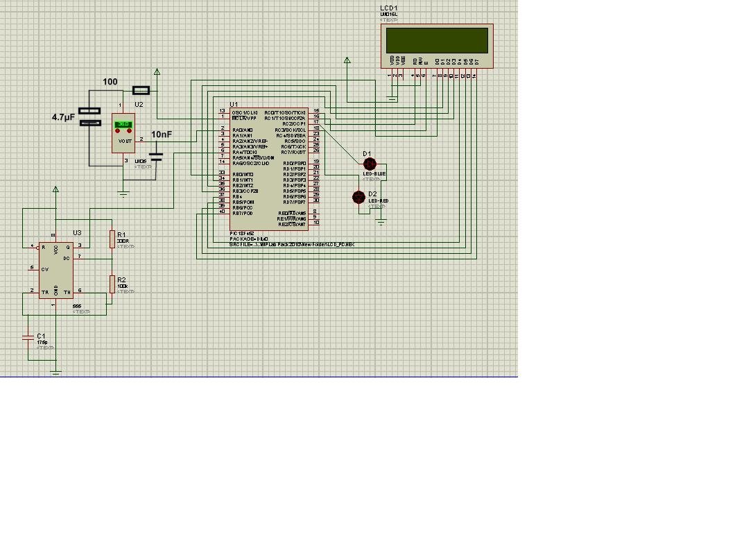
i am using PIC 18F452. I am trying to measure the temperature from LM35 ic and frequency from 555timer circuit and show them on LCD.
The problem is when i use higher value capacitor (in microf) in 555 circuit the values of temp are correctly shown on lcd but when i use low value capacitor (in nanof) the temp values become unstable e.g. if 25 is to be shown the values from 21 to 28 are displayed. the circuit works well in proteus.
probably there is problem with high frequency input or?
how i may solve it?


Thanks in advance
 

Ensure that the power lines are decoupled properly.

Measure the output of the LM35 and ensure that the voltage reading is stable. Measure the voltage at the PIC pin to which the LM35 signal goes.

Post the results.
 

i used 10uf decoupling capacitor
the output of LM35 is 241 and stable as seen by multimeter and same on the PIC pin AN0
but still the temperature displayed on lcd is fluctuating

thanks
 

Since you said that the circuit works well in Proteus, I assume the code is okay.

Connect 0.1uF ceramic capacitors across the power lines, especially the PIC VDD and VSS lines.
 

i tried but the problem still exists?
previously i had connected 10uf capacitor to pin 2 of 555 timer the temp displayed was correct and stable now as i have connected 47pf capacitor to pin 2 of 555 timer the temperature displayed is unstable i even removed the output of timer circuit from controller but problem still exists?


thanks
 
Last edited:

hello,

What is the link between LM35 temp and 555 timer ?
show us the schematic
and also the code
then we can help you..
 

there is no link b/w the 555 timer and LM35 but still with the low value capacitor at pin 2 of 555 the value of temp displayed become unstable
here is the code with attached circuit diagram of proteus

https://obrazki.elektroda.pl/3953499800_1361118485.jpg

and one warning that i am unable to eliminate

https://obrazki.elektroda.pl/2599625600_1361118665.jpg


code:


LIST P=18F452,r=hex,n=80,x=off,st=off

#include <P18F452.INC>

; Configuration bits
; ==================

CONFIG OSC=XT, PWRT=ON, BOR=OFF, WDT=OFF, LVP=OFF, DEBUG=OFF


LCD_DATA EQU PORTB
CTRL EQU PORTA
ADC EQU RA0
RS EQU RC0
RW EQU RA2
EN EQU RC1
CI EQU RA4
HT EQU RA5
FN EQU RA6
PH EQU 56H
PL EQU 55H
Q1L EQU 54H
Q1H EQU 53H
Q2 EQU 52H
Q3 EQU 51H


ORG 0000H


CLRF TRISC

MOVLW 30H ;TIMER1,16 BIT, INT-CLK, PRESCALER 1:8
MOVWF T1CON

;ADC CONFIGURE
BSF CTRL,ADC
MOVLW 0C1H
MOVWF ADCON0
MOVLW 8EH
MOVWF ADCON1
CALL DELAY


;COUNTER CONFIGURE

BSF PORTA,4
MOVLW 28H ;COUNTER, 16BIT
MOVWF T0CON
BCF INTCON,TMR0IF

;LCD CONFIGURE

CLRF TRISB
BCF CTRL,RS
BCF CTRL,RW
BCF CTRL,EN
CALL LDELAY
MOVLW 38H
CALL COMDWRT
CALL DELAY
MOVLW 0EH
CALL COMDWRT
CALL DELAY
MOVLW 80H
CALL COMDWRT
CALL DELAY
MOVLW A'T'
CALL DATAWRT
CALL DELAY
MOVLW 0C0H
CALL COMDWRT
CALL DELAY
MOVLW A'F'
CALL DATAWRT
CALL DELAY
MOVLW 87H
CALL COMDWRT
CALL DELAY
MOVLW 'º' ;DEGREE FOR CENTIGRADE
CALL DATAWRT
CALL DELAY
MOVLW 43H ;C
CALL DATAWRT
CALL DELAY


;PROCESSING TEMP

KK:
MOVWF 58H
BSF ADCON0,GO
BACKADC:BTFSC ADCON0,DONE
BRA BACKADC
MOVF ADRESL,W
CALL HEX2BCD
CALL BCD2ASCII
MOVLW 82H
CALL COMDWRT
CALL DELAY
CALL VALUEWRT

;processing humidity

CLRF TMR1H ;TMR1H MUST BE LOADED FIRST
CLRF TMR1L ;TMR1L MUST BE LOADED AFTER
CLRF TMR0H ;TMR0H MUST BE LOADED FIRST
CLRF TMR0L ;TMROL MUST BE LOADED AFTER
BSF T0CON,TMR0ON
CALL SEC_DLY
BCF T0CON,TMR0ON
MOVFF TMR0L,55H ;TMR0L MUST BE COPIED FIRST
MOVFF TMR0H,56H ;TMROH MUST BE COPIED AFTER
MOVLW 8EH ;36352 Hz IN DECIMAL
CPFSGT 56H
goto ho
goto co
ho:
BSF PORTC,2
BCF PORTC,3
goto KK
co:
BCF PORTC,2
BSF PORTC,3
goto KK


BRA KK


;CALL FUNCTIONS

VALUEWRT:
MOVF Q3,w
MOVWF LCD_DATA
BSF PORTC,0
;BCF CTRL,RW
BSF PORTC,1
CALL DELAY
BCF PORTC,1
MOVF Q2,w
MOVWF LCD_DATA
BSF PORTC,0
;BCF CTRL,RW
BSF PORTC,1
CALL DELAY
BCF PORTC,1
MOVLW 2EH
MOVWF LCD_DATA
BSF PORTC,0
;BCF CTRL,RW
BSF PORTC,1
CALL DELAY
BCF PORTC,1
MOVF Q1L,w
MOVWF LCD_DATA
BSF PORTC,0
;BCF CTRL,RW
BSF PORTC,1
CALL DELAY
BCF PORTC,1
MOVF PL,w
MOVWF LCD_DATA
BSF PORTC,0
;BCF CTRL,RW
BSF PORTC,1
CALL DELAY
BCF PORTC,1
RETURN

HEX2BCD:
CLRF PH
CLRF PL
CLRF Q1L
CLRF Q1H
CLRF Q2
CLRF Q3

MULLW 30H ;(30)h=(48)d use for converting measured hex value from adc
MOVFF PRODH,PH ;upper byte of product result
MOVFF PRODL,PL ;lower byte of product result
MOVLW 0AH
CLRF Q1L
VV: INCF Q1L
BC AA
VV1:SUBWF PL
BC VV
DECF PH
BN AA1
BRA VV
AA: INCF Q1H
BRA VV1
AA1:ADDWF PL
DECF Q1L
;*************
VV2:INCF Q2
SUBWF Q1L
BC VV2
DECF Q1H
BN AA2
BRA VV2
AA2:ADDWF Q1L
DECF Q2
;**************
VV3:INCF Q3
SUBWF Q2
BC VV3
ADDWF Q2
DECF Q3

return


BCD2ASCII:
MOVF 51H,W
IORLW 30H
MOVWF Q3
MOVF Q2,w
IORLW 30H
MOVWF Q2
MOVF Q1L,w
IORLW 30H
MOVWF Q1L
MOVF PL,w
IORLW 30H
MOVWF PL
RETURN


COMDWRT:
MOVWF LCD_DATA
BCF PORTC,0 ;RS=0
;BCF PORTC,1 ;R/W=0
BSF PORTC,1 ;EN=1
CALL DELAY
BCF PORTC,1 ;EN=0
RETURN


DATAWRT:
MOVWF LCD_DATA
BSF PORTC,0
;BCF CTRL,RW
BSF PORTC,1
CALL DELAY
BCF PORTC,1
RETURN

DELAY:
MOVLW 1FH
MOVWF 59H
AGAIN:
NOP
NOP
DECF 59,f
BNZ AGAIN
return

LDELAY:
MOVLW 5FH
MOVWF 59H
AGAIN1:
NOP
NOP
DECF 59,f
BNZ AGAIN1
return

SEC_DLY
CLRF TMR1L
CLRF TMR1H
BCF PIR1,TMR1IF
BSF T1CON,TMR1ON ;START TIMER
T1:BTFSS PIR1, TMR1IF
BRA T1
BCF PIR1,TMR1IF
BSF T1CON,TMR1ON ;START TIMER
T12:BTFSS PIR1, TMR1IF
BRA T12
BCF T1CON,TMR1ON ;STOP TIMER
return

END
 

I don't think is a problem due to the code (however I'm not able to check it). LM35 has a 10mV/degC slope, since you have 7 degC variation in the reading, it seems a 70mV noise is present on the LM35 output line. This could be due to crosstalk between 555 circuit and temperature sensor to PIC line.
You could try to put a simple LC (or probably even RC) filter close to the PIC pin to which the LM35 is connected.
Where did you place the biasing resistor of the L35: close to it or near the PIC ? Probably is better to place that resistor close to PIC in order to have current instead voltage flowing through the output line. Current is more difficult to interfere than voltage.
 

plz describe the RC filter circuit and i haven't used any resistor with LM35 as shown in the schematic so where to place it

thanks
 

hello,


As proposed in previous post,
Add a filter on the power supply of LM35 ...


If it is not enough to solve your probleme,
Try also to disable interrupt during ADC acquisition, and re-enable it after.
 

in order to check the modifications in LM35 circuit i grounded the RA4 pin of
PIC and then analyzed the effects
by using the modifications the output of LM35 was unstable
i have used 67ohm in place of 100 ohm resistor as was available nearer value
the addition and removal of resistor shows no effect on output of LM35.
with adding 10nF of capacitor at output and ground, the output of LM35 is unstable fluctuating b/w 31 to 21
by adding 4.7uf capacitor the displayed value was 24.96°C at 267mV which was 25.44°C without
it.

plz describe more about the interrupt


thanks
 

hello

in order to check the modifications in LM35 circuit i grounded the RA4 pin of
PIC and then analyzed the effects

so,no change on RA4 means without interruption !
=> no problem linked with interrupt.

don't forget you have only 1024bits for 5000mV so for scale= 500°C
1bit => 4.88mV
measure is +-1 bit so +- 0.488°C
25,44°C - 24,96°C= 0.48°C !!!
NORMAL


At least you can improve resolution by averaging your measurments
Add 10 times each individual raw ADC measure
and then convert it in °C
to display it by shifting 2 times the separator point to the left .

# raw value
1 254
2 255
3 254
4 254
5 255
6 254
7 255
8 255
9 254
10 255
total 2545
diplay 25,45


or use an 12bits ADC !!!
 

sir i meant to inform about the analysis that the without any i/p at RA4 the output of LM35 by using 4.7uF cap at VCC and ground is 0.48 less (not an issue) but the problem is the output of LM35 should be stable instead by using 10nF cap b/w output and ground the output is unstable fluctuating b/w 31°C to 21°C means still the problem is not solved as i require stable o/p of LM35 with 555 timer circuit with cap in pF range at pin 2 of 555.

thanks
 

cheetha, could you post exactly the circuit are you using, where we can see all the connections among LM35, PIC and 555 (and supplies as well) ?
 

hello,


Code:
PROCESSING TEMP

KK:	
MOVWF 58H
BSF ADCON0,GO
BACKADC:BTFSC ADCON0,DONE
BRA BACKADC
MOVF ADRESL,W
CALL HEX2BCD
CALL BCD2ASCII
MOVLW 82H
CALL COMDWRT
CALL DELAY
CALL VALUEWRT


MOVWF 58H <- what is that ?

you take ADRESL (low byte) of ADC value
What about ADRESH ?
only 8 bits as results ?


you must treat the result of ARRESH<<8 + ADRESL (if right shifted) to get 10 bits of resolution
or i missed something ???
 

sorry MOVWF 58H is a mistake, i think it is not effecting the system
and
8 bits are enough for measuring voltages in millivolts (0 to 100) from LM35 thats why i utilized only 8 bits.
i will be very thankful if you make corrections in code

thanks

- - - Updated - - -

albbg, are you asking about the picture of real circuit which is on project board ?
as it will be a little difficult of taking an intelligible picture due wiring ....

thanks
 

albbg, are you asking about the picture of real circuit which is on project board ?
as it will be a little difficult of taking an intelligible picture due wiring ....

thanks
Not a picture, but just the drawing of the schematic. If possible.
 

hello,


:???:please post your code between 2 balises
.... your code

:idea:and a good rule to get help from others :
- add many comment on your asm code !
- uses justification to increase the readability
because to much effort to read and understand what you wrote in your code...

change variable definition
CTRL EQU TRISA ; to define RA0 as input

use 10 bits for ADC
You have 8 bits only to define 500°C
LM35 gives 10mV/0C and 0mV at 0°C
250mV at 25°C
Measurement scale is 5V = 5000mV => 500°C
500/256 => ~2°C per bit
measure is allways +-1bit so +-2°C
In this case, it is Impossible to get accurate value.

you can use this subroutine to display 16bits word (10 bits from ADC)


Code:
; add these variable in your code
bdixmil
bmille
bcent
bdix
bun
btmp	
val1:2
val2:2
valx:2
Drapeaux	; multipurpose flags
;Drapeau:7= signe mesure temp 1=negatif 0=positif pour DS1624
;Drapeau:6= Elligibilite de stockage mesure
;Drapeau:5 =test si saisie binaire ou BCD
;Drapeau:4= choix format 1=999   0=65535 pour bcd53 (5 ou 3 digits)
;Drapeau:3= choix format 1=XX    0=XXX pour bcd3
;Drapeau:2= choix output 1=Rs232 0=LCD
;Drapeau:1= choix format 1=XXXX.X  0=XXXXX pour bcd5
;Drapeau:0= pour effacer zero inutile


;PROCESSING TEMP to modifiy

KK:	
	BSF ADCON0,GO
BACKADC:
	BTFSC ADCON0,DONE
	BRA BACKADC
	MOVF ADRESL,W
	movwf val1
	MOV ADRESH,W
	movwf val1+1
	bsf Drapeau,4  ; mode 5 digits   to see 00000 up to 01023
	call bcd53
	CALL DELAY


; routine to display word 16 bits value on LCD
; affichage word --> decimal 3 ou 5 digits
; si Drapeau,4=1 -> 000 a 999 sinon -> 0000 … 65535
; en entree val1 et val1+1  contiennent  le mot de 16 bits à afficher
; valx sert à sauvegarder cette valeur,qui est modifié dans le sous programme
; puis restituee en sortie de programme
; les variables intermediares bmille, bcent,bdix,bun servent à decortiquer la valeur en elements decimaux
; au passage on met le resultat en ascii

bcd53
	movf	val1,w	;LSB value
	movwf	valx
	movf	val1+1,w	;MSB value
	movwf	valx+1
	swapf  val1,w
	iorlw  0xf0
	movwf  bmille
	addwf  bmille,f
	addlw  0xE2

	movwf  bcent
	addlw  0x32
	movwf  bun
	movf   val1,w
	andlw  0x0F
	addwf  bcent,f
	addwf  bcent,f
	addwf  bun,f
	addlw  0xE9

	movwf  bdix
	addwf  bdix,f
	addwf  bdix,f
	swapf  val1+1,w
	andlw  0x0F
	addwf  bdix,f
	addwf  bun,f
	rlf    bdix,f
	rlf    bun,f
	comf   bun,f
	rlf    bun,f
	movf   val1+1,w
	andlw  0x0F
	addwf  bun,f
	rlf    bmille,f
	movlw  0x07
	movwf  bdixmil
        movlw  0x0A
Lb1:
 	addwf  bun,f
	decf   bdix,f
	btfss  STATUS,C
	goto   Lb1
Lb2:
	addwf  bdix,f
	decf   bcent,f
	btfss  STATUS,C
	goto   Lb2
Lb3:
       addwf  bcent,f
	decf   bmille,f
	btfss  STATUS,C
	goto   Lb3
Lb4:
	addwf  bmille,f
       decf   bdixmil,f
	btfss  STATUS,C
       goto   Lb4
       btfsc Drapeau,4		; mode 999 or 65535
	goto Lb5
	movf   bdixmil,w
  	addlw  '0'
	call LCD_Putchar	; envoi diz de milliers sur LCD 
	movf   bmille,w
	addlw  '0'
	call LCD_Putchar	; envoi milliers sur LCD 
Lb5:
	bcf Drapeau,4
	movf   bcent,w
  	addlw  '0'
	call LCD_Putchar	;envoi centaines sur LCD 
	movf   bdix,w
  	addlw  '0'
	call LCD_Putchar	;envoi dizaines sur LCD
	movf   bun,w
	addlw  '0'
 	call LCD_Putchar 	;envoi unites sur LCD 
; use below if you want to keep original values val1 & val1+1
;	movf valx,w
;	movwf val1
;	movf valx+1,w
;	movwf	val1+1
	return


LCD_Putchar:
; is your routine to display char on LCD
; after writing the car, the position on LCD must be increased
; your code .....
;
;
return

Use your own subroutine for displaying data on display instead of LCD_Putchar
You will see raw data of LM35 measure from ADC (0000 ..up to 1023)
you can later add decimal point to transform in °C
 

Thanks a lot for the code I will try it out
Since the temp of LM35 will hardly ever cross 50°C, mostly about 25°C that is why I used only 8 bits keeping logic and program simple, the inaccuracy b/w LM35 output and displayed value is not a problem
The output of LM35 and value displayed is up to desired and is stable so coding has no problem
but The problem is the output of LM35 become unstable when smaller value capacitor (in pF) is used at pin 2 of 555 timer and generated frequency is in KHz. The fluctuations are from 21 to 28 °C displayed value. so how to make the output of LM35 stable at smaller capacitance and higher i/p frequency from 555 and why it is happening


albbg, the schematic is same as shown

https://obrazki.elektroda.pl/3953499800_1361118485.jpg


Not a picture, but just the drawing of the schematic. If possible.

plz help

thanks
 

Status
Not open for further replies.

Similar threads

Part and Inventory Search

Welcome to EDABoard.com

Sponsor

Back
Top