Continue to Site

Welcome to EDAboard.com

Welcome to our site! EDAboard.com is an international Electronics Discussion Forum focused on EDA software, circuits, schematics, books, theory, papers, asic, pld, 8051, DSP, Network, RF, Analog Design, PCB, Service Manuals... and a whole lot more! To participate you need to register. Registration is free. Click here to register now.

PIC 18F ADC Problem (plz help)

Status
Not open for further replies.
There is actually nothing wrong with the Microchip C18 Compiler, it has compiled the code as instructed.

There are several minor issues and one main issue with your code.

Your main issue was the following line of code:

Code:
voltage = (ADRESH << 8) | ADRESL;

The assignment statement above assumes a implicit cast conversion of a Char type to an Integer type before the final result of calculations on the Right Hand Side (RHS) of the assignment.

This implicit cast conversion is neither ANSI Standard C nor traditional C (K&R), the rule of implicit assignment type conversion or promotion, as it is sometimes referred, is as follows:


MikroC clearly violates this rule, by the implicit type conversion of the ADRESH from type unsigned char to unsigned int before the final calculations of the RHS.

The proper way to carry out this assignment type conversion, as per ANSI Standard C rules, is as follows:

Code:
voltage = ((unsigned int)ADRESH << 8) | ADRESL;

Another option, if you do not wish to explicitly cast ADRESH from unsigned char to unsigned int, is as follows:

Code:
voltage = ADRESH;
voltage <<= 8;
voltage |= ADRESL;

In place of the statement above.

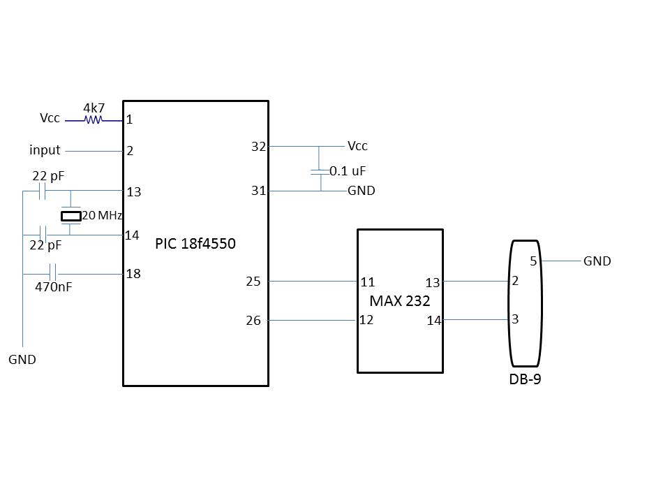
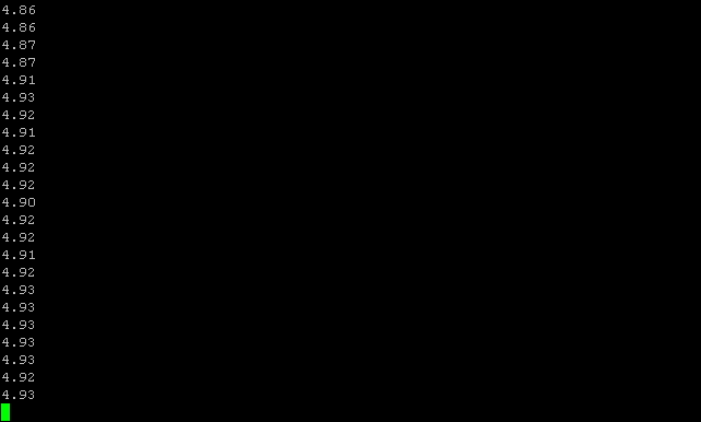
The following has been tested on a PIC18F4550 using Microchip C18 Compiler and yields the expected results:

Code:
#include <p18f4550.h>
#include <delays.h>

void Read_ADC(void);
void Send_Value (void);

unsigned int adc;
unsigned float result; 
unsigned int voltage;

void main(void)
{
	TRISA  = 0b00000001;
	ADCON0 = 0b00000001;	
		// A/D is ON
	ADCON1 = 0b00001110;	
		// Vref- set to Vss
		// Vref+ set to Vdd
		// AN0 is analog - others are digital
	ADCON2 = 0b10111111;
		// right justify
		// Acq time 20TAD
		// clk Frc
	TXSTA = 0b10100010;
		// 8-bit
		// async
		// low speed (BRGH=0)
	RCSTA = 0b10010000;
	SPBRG = 77;
	
	while (1)
	{	
		Read_ADC();
		Send_Value();
		Delay10KTCYx(240);		//Delay 200 ms
		Delay10KTCYx(240);		//Delay 200 ms
	}

}

void Read_ADC (void)
{
	voltage = 0;		//globally defined as unsigned long
    Delay10TCYx(24);       // Delay for 240TCY allow sampling cap to charge
	ADCON0bits.GO = 1;		//start converting
	while (ADCON0bits.DONE == 1);		//wait for EOC
	voltage = ((unsigned int)ADRESH << 8) | ADRESL;		//combines two bytes into a long int
	result = (float)(voltage * 5)/1023;
	adc = result * 1000;
	//voltage = voltage * 5000;			//Vref is in milliVolts
	//voltage = voltage/1023;			//10 bit ADC
}

void Send_Value (void)
{
	char ch;
	ch = (adc/1000) % 10;		//extract thousands digit
	ch = ch + 48;			// now it is in ASCII

	while (PIR1bits.TXIF == 0);
	{
		TXREG = ch;
	}

	while (PIR1bits.TXIF == 0);
	TXREG = '.';		//We need a decimal point
	

	ch = (adc/100) % 10;		//extract hundredth digit
	ch = ch + 48;
	while (PIR1bits.TXIF == 0);
	TXREG = ch;
	

	ch = (adc/10) % 10;		//extract tenth digit
	ch = ch + 48;
	while (PIR1bits.TXIF == 0);
	TXREG = ch;


	ch = adc % 10;		
	ch = ch + 48;
	while (PIR1bits.TXIF == 0);
	TXREG = ch;

	while (PIR1bits.TXIF == 0);
	TXREG = '\n';

	while (PIR1bits.TXIF == 0);
	TXREG = '\r';

	while (PIR1bits.TXIF == 0);
	
}


I should also mention the C18 Compiler comes with an extensive library of routines which could greatly simplify this task to only a few statements.

BigDog

Thank u so much. So the problem was that, I compiled your code in MPLAB and its working fine. The only problem is that the last digit is now showing. I think I need to follow Bjuric's suggestion of putting

while (TXSTA.TRMT == 0);

---------- Post added at 06:00 ---------- Previous post was at 05:57 ----------

Dude, did I even mentioned you?

I was referring to Paritoshgiri's code, check post #40.
Code:
unsigned long adc;
[B]unsigned float result;[/B]
unsigned int voltage;

I installed mikroC Pro v1.65 and compiled the code you send me and its working fine. The hex file is good and the results are correct. Thank u so much. I think there was compatibility problem of mikroC code with MPLAB. However, BigdogGuru's code is also working fine now in MPLAB. Thank u so much for your help. Take care :)
 

Is it not showing up on all of the UART output?

It maybe the terminal emulation settings and not the PIC program itself.

Are you using hyperterminal? I have tested the code using Putty, which in its default settings requires both a newline and carriage return.

BigDog

---------- Post added at 06:05 ---------- Previous post was at 06:01 ----------

By the way, the HiTech compiler has library routines which would replace of all the UART and ADC code. The use of the library routines would not only simply the program, it would provide more liable UART transmission.


BigDog
 

Is it not showing up on all of the UART output?

It maybe the terminal emulation settings and not the PIC program itself.

Are you using hyperterminal? I have tested the code using Putty, which in its default settings requires both a newline and carriage return.

BigDog

Yes I am using hyperterminal private edition. The new line and carriage return are there but not the last digit. For e.g. in 3.712 the last digit 2 is missing.

And how to use the UART library routine to simplify the code. Please give some suggestion on that...
 

Your original code was only setup for three significant digits, to display four significant digits you'll need to change and add the following:

Code:
void Read_ADC (void)
{
	voltage = 0;		//globally defined as unsigned long
    Delay10TCYx(24);       // Delay for 240TCY allow sampling cap to charge
	ADCON0bits.GO = 1;		//start converting
	while (ADCON0bits.DONE == 1);		//wait for EOC
	voltage = ((unsigned int)ADRESH << 8) | ADRESL;		//combines two bytes into a long int
	result = (float)(voltage * 5)/1023;
	adc = result * [COLOR="#FF0000"]10000[/COLOR];
	//voltage = voltage * 5000;			//Vref is in milliVolts
	//voltage = voltage/1023;			//10 bit ADC
}

void Send_Value (void)
{
	char ch;

[COLOR="#FF0000"]	ch = (adc/10000) % 10;		//extract ten thousands digit
	ch = ch + 48;			// now it is in ASCII

	while (PIR1bits.TXIF == 0);
	{
		TXREG = ch;
	}[/COLOR]

[COLOR="#FF0000"]	while (PIR1bits.TXIF == 0);  //MOVED
	TXREG = '.';		//We need a decimal point MOVED[/COLOR]
   
	ch = (adc/1000) % 10;		//extract thousands digit
	ch = ch + 48;			// now it is in ASCII

	while (PIR1bits.TXIF == 0);
	{
		TXREG = ch;
	}
	

	ch = (adc/100) % 10;		//extract hundredth digit
	ch = ch + 48;
	while (PIR1bits.TXIF == 0);
	TXREG = ch;
	

	ch = (adc/10) % 10;		//extract tenth digit
	ch = ch + 48;
	while (PIR1bits.TXIF == 0);
	TXREG = ch;


	ch = adc % 10;		
	ch = ch + 48;
	while (PIR1bits.TXIF == 0);
	TXREG = ch;

	while (PIR1bits.TXIF == 0);
	TXREG = '\n';

	while (PIR1bits.TXIF == 0);
	TXREG = '\r';

	while (PIR1bits.TXIF == 0);
	
}

I haven't tested these code changes, run them and let me know the outcome.

BigDog

Its working perfectly fine now. Thank u so much for your help :)
 

If I have the time tomorrow, I'll write an equivalent program using the HiTech libraries for your future reference.

BigDog
 

This is called BigDogGuru Magic.
Such nonstandard implicit cast conversions can easily become a hindrance, rather than a benefit. Not to mention the aggravation encountered when coding on an ANSI Standard C Compliant Compiler after relying on nonstandard practices of the Non-compliant MikroC compiler.

This is what one of our computer sc. Professors used to tell us.
 

I've one more question. If i want to speed up the baud rate upto 115200, can i just make a calculation and change the SPBRG value or do i need to change anything else in the code? Moreover, can the ADC give out the value at that speed? Please help.
 

If i want to speed up the baud rate upto 115200, can i just make a calculation and change the SPBRG value or do i need to change anything else in the code?

Whenever you are configuring the BAUD rate of a UART/USART of a microcontroller, you must first examine the potential %Error of the desired BAUD rate.

This can be accomplished by either the use of BAUD rate calculator, like the link previously provide:

PIC Microcontroller RS232 IO SPBRG Calculator

With the aid of some datasheets, unfortunately the PIC18F4550 Datasheet only covers a system clock up to 40MHz, Or by carrying out the calculations by hand.


If you examine the calculated table:


Fortunately, the PIC18F4550 @ 48MHz can be successfully configured at a BAUD rate of 115,200 with a %Error of -0.2%, which is more than acceptable.

However, you should also notice the BAUD rate of 115,200 is only available with a BRGH = 1, not with a BRGH = 0 setting.

Therefore if the Oscillator Configuration Bits remain unchanged, a BAUD rate of 115,200 should be achieved by setting BRGH = 1 and SPBRG = 25.


Moreover, can the ADC give out the value at that speed? Please help.

The code snippet currently employed:

Code:
while (1)
{	
	Read_ADC();                       [COLOR="#FF0000"]// ADC Value is obtained[/COLOR]
	Send_Value();                     [COLOR="#FF0000"]// Value is formatted and then transmitted[/COLOR]
	Delay10KTCYx(240);		//Delay 200 ms
	Delay10KTCYx(240);		//Delay 200 ms
}

The sample rate of the ADC module is the constraining factor of code execution, not the serial transmission rate.

The value is first obtained by Read_ADC() and then is transmitted serially.

So to answer your question, the increased BAUD rate should not present any issues. You are in fact sampling the voltage at the same rate, only transmitting these results to your PC at a faster rate.

BigDog
 

Whenever you are configuring the BAUD rate of a UART/USART of a microcontroller, you must first examine the potential %Error of the desired BAUD rate.

This can be accomplished by either the use of BAUD rate calculator, like the link previously provide:

PIC Microcontroller RS232 IO SPBRG Calculator

With the aid of some datasheets, unfortunately the PIC18F4550 Datasheet only covers a system clock up to 40MHz, Or by carrying out the calculations by hand.


If you examine the calculated table:


Fortunately, the PIC18F4550 @ 48MHz can be successfully configured at a BAUD rate of 115,200 with a %Error of -0.2%, which is more than acceptable.

However, you should also notice the BAUD rate of 115,200 is only available with a BRGH = 1, not with a BRGH = 0 setting.

Therefore if the Oscillator Configuration Bits remain unchanged, a BAUD rate of 115,200 should be achieved by setting BRGH = 1 and SPBRG = 25.


The code snippet currently employed:

Code:
while (1)
{	
	Read_ADC();                       [COLOR="#FF0000"]// ADC Value is obtained[/COLOR]
	Send_Value();                     [COLOR="#FF0000"]// Value is formatted and then transmitted[/COLOR]
	Delay10KTCYx(240);		//Delay 200 ms
	Delay10KTCYx(240);		//Delay 200 ms
}

The sample rate of the ADC module is the constraining factor of code execution, not the serial transmission rate.

The value is first obtained by Read_ADC() and then is transmitted serially.

So to answer your question, the increased BAUD rate should not present any issues. You are in fact sampling the voltage at the same rate, only transmitting these results to your PC at a faster rate.

BigDog

When I calculated the SPBRG value using a formula for 48 MHz and 115200 baud rate, i got the value 6. So according to your table, I can't use SPBRG = 6;
Do I need to use like this:

Code:
SPBRBG = 25;
BRGH = 1;
Also, if i want the digital output from ADC very fast, what can I do? Moreover, how to increase the sample rate of ADC module? Do I need to increase the value of crystal frequency for that or do I need to change anything in code? Please help.
 

The code I posted was wrong. Sorry for that. I think I should do

TXSTA = 0b10100110; //Set BRGH = 1;
SPPBRG = 25;

Can you answer my second question please about increasing the sample rate of ADC module? I want to get the digital output from analog input in real time. Is it possible?
 

I intended to respond to your post, however I've been exceedingly busy tonight.

The code I posted was wrong. Sorry for that. I think I should do

TXSTA = 0b10100110; //Set BRGH = 1;
SPPBRG = 25;

Correct, that should setup your UART for a BAUD rate of 115,200.

Just in case you haven't come across it as yet, there are three different variations of the formula used to calculate the BAUD rate depending on the configuration of the UART.

Reference: PIC18F4550 Datasheet, Section: 20.1 Baud Rate Generator (BRG), TABLE 20-1, pg 247

Fosc/[64 (n + 1)], Fosc/[16 (n + 1)], Fosc/[4 (n + 1)], where n = value of SPBRGH:SPBRG register pair

When BRG16 = 0 and BRGH = 1, you'll need to use the Fosc/[16 (n + 1)] form with 16 in place of 64.


Can you answer my second question please about increasing the sample rate of ADC module?

You can increase the ADC conversion rate by tweaking the ACQT2:ACQT0: A/D Acquisition Time Select bits and ADCS2:ADCS0: A/D Conversion Clock Select bits. However once the current ADC has been completed, code execution is still dependent on formatting the result and transmit the formatted data to your PC before the next ADC can begin.

If you want the ADC module to continuously sample and perform the conversion independent of the code execution, you would need to the ADC interrupts. However, a possible bottleneck can still occur due to the time required to format the data and transmit the results to your PC. If the ADC sample rate exceeds the time required to carry out the two aforementioned tasks, then the increase ADC rate is for naught.


I want to get the digital output from analog input in real time. Is it possible?

It depends on your definition of Real Time. In reality No. There will always be some latency due to ADC conversion time, time required to format the data and then transmit the value via serial to your PC.


BigDog
 

I intended to respond to your post, however I've been exceedingly busy tonight.


Correct, that should setup your UART for a BAUD rate of 115,200.

Just in case you haven't come across it as yet, there are three different variations of the formula used to calculate the BAUD rate depending on the configuration of the UART.

Reference: PIC18F4550 Datasheet, Section: 20.1 Baud Rate Generator (BRG), TABLE 20-1, pg 247

Fosc/[64 (n + 1)], Fosc/[16 (n + 1)], Fosc/[4 (n + 1)], where n = value of SPBRGH:SPBRG register pair

When BRG16 = 0 and BRGH = 1, you'll need to use the Fosc/[16 (n + 1)] form with 16 in place of 64.


You can increase the ADC conversion rate by tweaking the ACQT2:ACQT0: A/D Acquisition Time Select bits and ADCS2:ADCS0: A/D Conversion Clock Select bits. However once the current ADC has been completed, code execution is still dependent on formatting the result and transmit the formatted data to your PC before the next ADC can begin.

If you want the ADC module to continuously sample and perform the conversion independent of the code execution, you would need to the ADC interrupts. However, a possible bottleneck can still occur due to the time required to format the data and transmit the results to your PC. If the ADC sample rate exceeds the time required to carry out the two aforementioned tasks, then the increase ADC rate is for naught.


It depends on your definition of Real Time. In reality No. There will always be some latency due to ADC conversion time, time required to format the data and then transmit the value via serial to your PC.


BigDog

Thank you for all the suggestion. ADC is working fine when the input voltage change slowly but in my case the input voltage change very fast, so in that case, many values are missed and sometimes when the input voltage starts changing rapidly, the data in the hyperterminal stops. What might be the reason behind it and what can I do to speed up the conversion process so that it is suitable for rapidly changing input voltage. Please help.
 

ADC is working fine when the input voltage change slowly but in my case the input voltage change very fast, so in that case, many values are missed and sometimes when the input voltage starts changing rapidly, the data in the hyperterminal stops.

What is the highest frequency component of interest? What type of sensor is attached to the PIC's ADC module. Have you successfully increased the BAUD rate to 115200?

What might be the reason behind it and what can I do to speed up the conversion process so that it is suitable for rapidly changing input voltage. Please help.

I'll need to take another look at your code. Can you post the latest version with a schematic of the circuit?

BigDog
 

What is the highest frequency component of interest? What type of sensor is attached to the PIC's ADC module. Have you successfully increased the BAUD rate to 115200?


I'll need to take another look at your code. Can you post the latest version with a schematic of the circuit?

BigDog

The sensor attached to PIC's ADC module is displacement sensor. I am not really sure about the highest frequency component. And also, I tried to increase the baud rate to 115200 but its not working. It is only working well for 9600 bps. I just changed:

TXSTA = 0b10100110; //Set BRGH = 1;
SPPBRG = 25;

but still its not working. The hyperterminal doesn't show any data.

Here's my code:
Code:
#include <p18f4550.h>
#include <delays.h>

void Read_ADC(void);
void Send_Value (void);

unsigned int adc;
unsigned float result; 
unsigned int voltage;

void main(void)
{
	TRISA  = 0b00000001;
	ADCON0 = 0b00000001;	
		// A/D is ON
	ADCON1 = 0b00001110;	
		// Vref- set to Vss
		// Vref+ set to Vdd
		// AN0 is analog - others are digital
	ADCON2 = 0b10111111;
		// right justify
		// Acq time 20TAD
		// clk Frc
	TXSTA = 0b10100010;
		// 8-bit
		// async
		// low speed (BRGH=0)
	RCSTA = 0b10010000;
	SPBRG = 77;
	
	while (1)
	{	
		Read_ADC();
		Send_Value();
		Delay10KTCYx(240);		//Delay 200 ms
		Delay10KTCYx(240);		//Delay 200 ms
	}

}

void Read_ADC (void)
{
	voltage = 0;		//globally defined as unsigned long
    Delay10TCYx(24);       // Delay for 240TCY allow sampling cap to charge
	ADCON0bits.GO = 1;		//start converting
	while (ADCON0bits.DONE == 1);		//wait for EOC
	voltage = ((unsigned int)ADRESH << 8) | ADRESL;		//combines two bytes into a long int
	result = (float)(voltage * 5)/1023;
	adc = result * 10000;
	//voltage = voltage * 5000;			//Vref is in milliVolts
	//voltage = voltage/1023;			//10 bit ADC
}

void Send_Value (void)
{
	char ch;
	ch = (adc/10000) % 10;		//extract thousands digit
	ch = ch + 48;			// now it is in ASCII

	while (PIR1bits.TXIF == 0);
	{
		TXREG = ch;
	}

	
	while (PIR1bits.TXIF == 0);
	TXREG = '.';		//We need a decimal point

	ch = (adc/1000) % 10;		//extract thousands digit
	ch = ch + 48;			// now it is in ASCII

	while (PIR1bits.TXIF == 0);
	{
		TXREG = ch;
	}
	

	ch = (adc/100) % 10;		//extract hundredth digit
	ch = ch + 48;
	while (PIR1bits.TXIF == 0);
	TXREG = ch;
	

	ch = (adc/10) % 10;		//extract tenth digit
	ch = ch + 48;
	while (PIR1bits.TXIF == 0);
	TXREG = ch;


	ch = adc % 10;		
	ch = ch + 48;
	while (PIR1bits.TXIF == 0);
	TXREG = ch;

	while (PIR1bits.TXIF == 0);
	TXREG = '\n';

	while (PIR1bits.TXIF == 0);
	TXREG = '\r';

	while (PIR1bits.TXIF == 0);
}

and here's the schematics. Please help...


The sensor attached to PIC's ADC module is displacement sensor. I am not really sure about the highest frequency component. And also, I tried to increase the baud rate to 115200 but its not working. It is only working well for 9600 bps. I just changed:

TXSTA = 0b10100110; //Set BRGH = 1;
SPPBRG = 25;

but still its not working. The hyperterminal doesn't show any data.

I'll take a look at your code.

Do you have any other information concerning the sensor, manufacture, model number, datasheet, etc?

BigDog
 

I'll take a look at your code.

Do you have any other information concerning the sensor, manufacture, model number, datasheet, etc?

BigDog

I don't have much information about the sensor. Its a displacement sensor which gives output from -10V to +10V for -30mm to +30mm displacement. So, I used a resistor circuit to drop down the voltage level between 1 and 4.5V.

Here's the output pin diagram of the sensor. Please help.....
28_1326456091.jpg
 

How about the manufacturer and model number of the sensor?

Also how do you ensure the sensors output stays only in the positive range with only a resistor circuit?

The PIC's ADC module cannot handle negative voltages. A negative voltage applied to any of ADC channels can cause erratic behavior or seriously damage the PIC.

BigDog
 

Also how do you ensure the sensors output stays only in the positive range with only a resistor circuit?

The PIC's ADC module cannot handle negative voltages. A negative voltage applied to any of ADC channels can cause erratic behavior or seriously damage the PIC.


Take a closer attention to this. In my experience PIC freezes when negative voltage is applied to the ADC.
 

Status
Not open for further replies.

Similar threads

Part and Inventory Search

Welcome to EDABoard.com

Sponsor

Back
Top