Continue to Site

Welcome to EDAboard.com

Welcome to our site! EDAboard.com is an international Electronics Discussion Forum focused on EDA software, circuits, schematics, books, theory, papers, asic, pld, 8051, DSP, Network, RF, Analog Design, PCB, Service Manuals... and a whole lot more! To participate you need to register. Registration is free. Click here to register now.

[SOLVED] Pic 16f876a Pure Sinewave inverter

Status
Not open for further replies.
Fvm is right.........

The software is written in CCS C language which is very much different than ordinary C language used for PIC microcontrollers, you can't mix the code untill the format of the code is same because you cant compile any software written in different formats in a single software, you have to follow the rules of science.............:)
 

FvM Thanks for reply. Flowcode is very easy PIC coding application alike flow chart see Matrix Multimedia - Flowcode v2 - rapid electronic development kits there is a macro available to insert C code but I am not sure how much lenght it can accept. I will try to do the same with a copy of the existing code to know how it can help me.

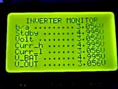
Actually the inverter project will be very nice if we can add a LCD display which shows the actual readings of the current, voltage, frequency, power and battery condition etc. and some fault messages as well. Further we can add a 3 stage smart charger with the circuit that is why I am trying to contribute something if I can.
 

I would recomend you to add one more MCU which can controll all important stuf.
BTW I intend to do exactly what I said. One more MCU which will controll all analog inputs of 16F876A, also it will show all those values on the LCD (or GLCD) and will be connected over RS485, as a slave, to the master, which controls also some other things.
I think this is easyest solution, becouse you don't need to study inverter code. You just control few important points of the inverter.
But everything depens on you, how much time you decide to spend on this project, a level of your knowledge is very important and so on ...

Regards
 

Thanks it is also a very good idea I will try the same.
 

Californiajoe is right because the current software occupies sufficient space in MCU memory and according to specification if we increase the size it will effect the performance significantly......

so using another MCU is an excellent idea...othewise we have to change MCU in other words we have to write the code again.......
 

The idea and explanations given by each is wonderful, Can anybody explain the concepts of the ADC check for inverter feedback and how it is done. The same can be used for current detection too?
thanks
Hari
 

I intend to use a 18F458 for controling analog inputs of the 16F876A. I just have to check input impedance of PORTA on "458. Maybe I will use voltage amplifiers for its inputs.
Range of inverter feedback voltage is from 0 to 5 V, so this shouldn't be a problem. I'll try to do some test version of measuring device in few days and it will be posted here.

Regards
 

Today I finally finished inverter on the protoboard and it works at the momment with one small transformer just for test, jami's code (last posted) was used.
One question: how did you solve a problem of the cooling for output transistors?

regards
 

using sinks can resolve the problem, because the software have built in overheat protection so it shuts down if transistors overheat significantly

Note....NTC in the circuit is not an ordinary resistor but a temperature sensor resistor........use sink paste for better performance and colling of the transistors......because sink paste absorbs all the heat quickly and efficiently rather than sinks alone.......it is available easily in the market, also try to keep the fan near the transistors....so the issue is resolved
 
Thanks jami007.
I already put together code for two channel voltmeter 0-5VDC. Now we have to transform all those inverter feedback signals in to real values. Any ideas would be appreciated.
Also I have available LCD 2x16 and GLCD 128x64 by the hand, what would be the best to show results on our "Inverter Monitor"?

Regards
 

I think a 2x20 or 4x16 LCD is good for display. Further anybody can suggest me why a HA1AA1 optocoupler for zero crossing detection is it helping in inverter operation? if it is used only to switch the bypass relay in inverter/power mode a 220VAC relay can do the job isn't it?
 

Well, you are to late. I already made GLCD version of a code.
 

Attachments

  • DSC00189.rar
    4.2 MB · Views: 1,257

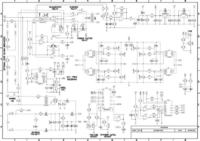
Here is the preliminary incomplete schematic with some additions for the review and suggestion of seniors.
 

Attachments

  • PSI_V001.pdf
    44.2 KB · Views: 607

hmmmm.....i think you want to show the values on front panel... I suggest dont do complicated job.....just show your input output,currents and battery voltage.....but if you can do the job and if you want to show all for easy interface so that you can check your inverter for proper working its an excellent idea....also you need an ADC for this purpose so using MCU is the best choice and also you can use it for other additional options too...you can use LCD or GLCD...a GLCD can show multiple values at the same time but also it increase the cost....so keep the size of it as small as possible...

Best of Luck

---------- Post added at 18:06 ---------- Previous post was at 17:31 ----------

v_rajaji read the artical from first post of Californiajoe probably from page 16...all your questions regarding circuit were answered before

---------- Post added at 18:15 ---------- Previous post was at 18:06 ----------

I made this project in about 80-90 US dollrars with extra componets purchased for safety (i.e 3 IC's instead of 1, excluding MCU) including some for reserch and testing Purposes .....i think one can make 2 of them easily in about 90-100 US dollars, because about 50% of money was invested on transformers.....
 

My project of "Inverter Monitor" will include also RS485 module, and through this module I will have remote acces to the inverter.
The question of cost is not important at the momment, becouse I have all required components in stock. Ofcouse for serial production would be the question of cost very important.

Regards
 

Why to download 4.21Mb when it contains
94_1285024364.jpg
only this pic.:roll::x
 
Last edited:

Hi Fvm, Californiajoe, jami007, v_rajaji!!!It's me!:grin:
Sorry! These days I've been very busy!!

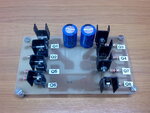
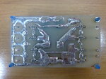
LCD, I think a great idea!Congratulations. I have a doubt about this inverter. I was try a 2 light of 60W (My transformer is the 150W). The 2 light bright very good, but my voltage fall 230Vac to 166Vac. I designed this PCB to H-bridge driver. Look the photo!

Best regards!!
 

Attachments

  • top.jpg
    top.jpg
    522.6 KB · Views: 307
  • bottom.jpg
    bottom.jpg
    578.9 KB · Views: 262

Daniell0_85, I suggest to you to take one bigger cooler for cooling of output tranistors, also you should have NTC resistor termically connected to cooler, so it can take care about temperature of transistors.
Also when you have 2 x 60W connected to the transformer, you should adjust RT1 to get 230VAC. But be carefull, your inverter should not work without load (2x60W) on the transformer, becouse output voltage would be much higher without load.

Regards
 

Output keeps on decreasing when temperature of MOSFETs keep on increasing, and after a certain temperature point it shuts down automatically to prevent damage. its an excellent built in feature of this modern technolong, so keep them cool and enjoy
 

Hello all.
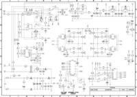
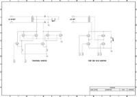
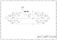
Please have a look on completed schematic of the inverter (excluding PIC connections and charger). I have a doubt here how to wire the circuit for charger! in case it is a traditional inverter it is quite simple to attach a charger on the same transformer (See 2nd attachment). Anybody can suggest me the ways to connect a charger on the same transformer with out using a big relay.


---------- Post added at 06:24 ---------- Previous post was at 05:16 ----------

I hope that I can wire the charger in this way is it correct?


---------- Post added at 07:39 ---------- Previous post was at 06:24 ----------

Revised schematic with minor corrections and additions.
 
Status
Not open for further replies.

Part and Inventory Search

Welcome to EDABoard.com

Sponsor

Back
Top