Continue to Site

Welcome to EDAboard.com

Welcome to our site! EDAboard.com is an international Electronics Discussion Forum focused on EDA software, circuits, schematics, books, theory, papers, asic, pld, 8051, DSP, Network, RF, Analog Design, PCB, Service Manuals... and a whole lot more! To participate you need to register. Registration is free. Click here to register now.

[SOLVED] Pic 16f876a Pure Sinewave inverter

Status
Not open for further replies.
Note: I connected the PIN GND of the TLP250 (U3 and U4) to GND to my inverter does work.
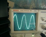
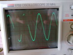
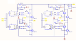
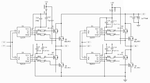
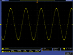
You mean the highside gate drivers? Strange.
 

Hi Californiajoe & FvM!:)

Yes Fvm, I mean the highside gate drivers. Californiajoe I've used the following componentes:

- IRFB330 for the IRL3803
- TLP250F for the TLP250

I attached the datasheet. I changed this component because is more cheaper than original component. Yes, I've output filter connected, but it's different to this schematic, this filter is good for my transformer.

Regards:grin:
 

Attachments

  • IRFB330.pdf
    430 KB · Views: 480
  • TLP250F.pdf
    120.1 KB · Views: 374

daniello you are using old version of software if I'm rigth it is named as ( sine_pwm_voltage-regulator_32_int_05.02.2009.hex ) you may need to change values in software for better results. my attachment includes all versions of softwares, using them you must have output as like as shown below (posted by people who made it successfully), also try the filter as in schematic
 

Attachments

  • output wave.jpg
    output wave.jpg
    206.4 KB · Views: 209
  • Photo043.jpg
    Photo043.jpg
    560.9 KB · Views: 215

I mean the highside gate drivers.
You maintained the bootstrap circuit to supply TLP250.VCC pin but changed connection TLP250.GND to circuit ground?
 

jami007 I will try your all software file than you attached of the page 18 (source_code_1908.zip ): https://www.edaboard.com/threads/96053/

FvM, you can see my connection in this picture.:grin:

Best regards
 

Attachments

  • Connection TLP250.png
    Connection TLP250.png
    81 KB · Views: 462

So you removed the bootstrap circuit completely. That's bad, because Q1 - Q4 won't fully switch on this case, resulting in a considerable output voltage reduction and excessive losses.
 

Ah!:-oOK!! FvM I'm understanding you tell me. If I connect PIN 5 of TLP250 (U3 & U4) to ground I will not have +U in the output B. The supply of the capacitors will excite the transistor. So Q1 - Q4 won't fully switch.

You're right. I will check it. The correct circuit is like the picture? Vcc of TLP250 is 10V or +U? Thank you very much
Best regards:grin:
 

Attachments

  • connection output.png
    connection output.png
    86.9 KB · Views: 317

Yes, the bootstrap circuit is correct now. It's according to tanner's original schematic, as far as I understand. As discussed in the forum before, 10V gate driver supply will fail the specified minimum voltage of 10V for TLP250 by one diode voltage drop. Toshiba has a recommendation of 15 V in the datasheet (the full version, not the short version linked below). It has been suggested in the forum to supply the gate drivers by the 12V battery voltage directly, or use a 12V LDO instead of a 10V regulator to supply them. Personally, I don't know the exact drop out voltage of TLP250, but one should try to keep the manufacturer specification.
 

it is safe and recommended to connect it with U+, because TLP250's minimum working voltage is 10V in the datasheet
 

Jami007,
Can you plz upload your latest circuit along with software C code and hex file? I appreciate your effort in this circuit.

Elara.
 

cvssrinivas here it is,

updated 14-11-2010
 

Attachments

  • Inverter.zip
    1.7 MB · Views: 1,149
Last edited:

Hi everybody!It's me!
You are right FvM! All my switch does work correctly. I've changed the pin 5 of TLP250 and I connected it like the circuit. Thank you very much!!My error in other post is the voltage b/a was wrong (>2V) :-D

Note: Voltage b/a must be (1-2) V

Now my output are:
DC -> AC
--------------
12 Vdc -> 237 Vac
11.6 Vdc -> 228.6 Vac
12.6 Vdc -> 248 Vac
13.5 Vdc -> 265.8 Vac

Look my photo! Although I want to solved the filter or PWM because it appear the peak between half positive wave adn half negative wave. My filter is different but I think that the problem is PWM. I will try your source code jami007!

Best regards!!!
 

Attachments

  • sine wave.png
    sine wave.png
    43.9 KB · Views: 225

Great!

Did you try to connect some working power to transformer, for example some light of 50W (100W, 150W)? Also measure the voltage!

Regards
 

Hi Californiajoe & jami007.

I will try your source code jami007 and I will connect a light 60W. I hope it does work!!

Best regards:grin:
 

FvM/Jami/Daniello/Californiajoe,

I am planning to use PIC30F2010 instead of PIC16f876A. Can you please let us know what changes we need to make in the circuit along with C source code also?

With Regards,
Elara.
 

if pin configuration is same you can use the same software by compiling it for your MCU but if it is different than you need to change all software for particular pin #, i.e according to your MCU pin configuration
 

PIC compiler help
I need help knowing PIC compiler possibilities since I am not well experienced of PIC programming in Basic or C, I use to program PIC by 'Flowcode' application. So can I mix this inverter's code with flowcode's code because I want to add some additional functions to the inverter.
 

I am planning to use PIC30F2010 instead of PIC16f876A.
The present software is based on CCS C built-in functions for ADC, PWM and timer interrupt operation. Although dsPIC/PIC24 are partly pin compatible to PIC 16/18, the integrated peripherals are quite different. The respective parts of the software must be redesigned. The most important point is to understand exactly, what the original software does. Otherwise you shouldn't try.

P.S.: To refer to the other software question

So can I mix this inverter's code with flowcode's code
At first sight, this would depend on the "flowcode" tool's ability to include native C code. I don't know anything about it. But looking at the present firmware, I guess it can't work without complete rearrangement of the code. It's too much low level hacker's code that can't coexist with other tasks easily.
 
Last edited:
Status
Not open for further replies.

Part and Inventory Search

Welcome to EDABoard.com

Sponsor

Back
Top