Continue to Site

Welcome to EDAboard.com

Welcome to our site! EDAboard.com is an international Electronics Discussion Forum focused on EDA software, circuits, schematics, books, theory, papers, asic, pld, 8051, DSP, Network, RF, Analog Design, PCB, Service Manuals... and a whole lot more! To participate you need to register. Registration is free. Click here to register now.

Photodiode Amplifier - BW Problem

Status
Not open for further replies.
They are all a lot faster than I would be looking for in your case. The TSH350 and EL5191 are current feedback, so not a good choice. EL1516 may be OK but there is no Spice model. It claims to be an improved EL2227 and I have a model for that and it looks OK, but the EL1516 has a lot higher bandwidth. 2.2k feedback would require around 2.2pF across it and give 50MHz bandwidth. The LT1806 seems a little peaky at first look - I would need to look in more detail to find out why. If you could find something with a lower bandwidth (e.g. EL2227) then I would think you are less likely to have problems.

Keith.
 
Hi Keith,

Thanks a lot for your answer.
I found this opamp OPA380 wich I realize is very similar to the THS4031 you recommended me.

I did the following configuration/simulation and think it will be ok for my project. In fact I was thinking to use the OPA2380 wich is a double OPA380. I think I can take advantage of it because it have the input and output pins on the same side of the package, so the PCB routing will be easiest and better from RF point of view.
Circuit
TI_OPA380.JPG
Freq. Response
Transmitance_OPA380.jpg

Could you please give me your opinion? I'm thinking to ask for some samples to TI.

Best regards!
Horacio
 

Horacio,

Yes that looks good. I did a quick simulation and came to the same conclusion - 3.3pF for compensation with 2.2k. Transient looks OK as well. You should be able to run it directly from 5V/0V because you have a constant bias current from your laser anyway.

Keith
 
Horacio,

Yes that looks good. I did a quick simulation and came to the same conclusion - 3.3pF for compensation with 2.2k. Transient looks OK as well. You should be able to run it directly from 5V/0V because you have a constant bias current from your laser anyway.

Keith

Thanks a lot Keith!
I'm going to build it and post a feedback as soon as possible.
Regards!
Horacio
 

Make sure there is some capacitance across that feedback ;)

Keith.

Hi Keith!,

How are you? I wish you a Happy new year!!

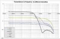
Finally I made the circuit with the OPA380 and I didn't found any problem with it. I realized the BW frequency cutoff is imposed by the photodiode due the high intensity it is exposed.

Please take a look at the attached graphic. You'll see different curves for different ligth intensities (using different optical filters) for the same circuit and set up.

For the lowest intensities (blue curve), the photodiode is not doing a bandwidth cutting and you can see the amplifier is working ok.


Now I'm trying to recompose a square signal for different frequencies (from 100Hz up to 1MHz) using pre/de-emphasis techniques in order to extend the bandwith when high intensities is used. Do you know something about that subject? I'll really appreciate your help.
Maybe we can continue in a new post.

Thanks a lot for your kind help!
Best regards.
 

Is the Y axis volts? Are you using a square wave drive? How do you know it is the photodiode that is limiting the response and not the opamp due to slew rate limiting?

Anyway, I will look properly when I am back at work tomorrow.

Keith
 
I have had a quick look and the opamp shouldn't be slew rate limiting. Two other questions: what is the photodiode and are you varying the laser modulation by optical filters rather than changing the modulation electronically?

Keith.
 
I would test the photodiode with a 50 ohm load, if there's a similar effect.

And check the OP output waveform.
 
Hi Keith,

Thanks for your answer.

I have had a quick look and the opamp shouldn't be slew rate limiting. Two other questions: what is the photodiode and are you varying the laser modulation by optical filters rather than changing the modulation electronically?

Keith.

- The y axis is the transmitance in [V/V]. The output to input ratio, this is the sinusoidal wave output to the sinusoidal wave input of the generator. I'm using 200mVpk-pk amplitude.

- The photodiode is the Vishay BPW24R.

- I'm modulating the laser electronically with a sinusoidal wave generator and the optical filters are used in order to attenuate the DC light intensity, to don't saturate the photodiode.

The roll off is you can see in the graphic the ligth intensity because is very high. It's above the photodiode specifications.

The curves where measured with sinusoidal waves. But I will test the performance of the system with square waves, in order to see how this kind of signal is degenerated and how can I implement and algorithm to recover as much as I can. I'm working on an algorithm to accomplish this.

Best regards,
keep in touch!
Horacio

---------- Post added at 13:05 ---------- Previous post was at 13:00 ----------

I would test the photodiode with a 50 ohm load, if there's a similar effect.

And check the OP output waveform.

Hi FvM,

Thanks for your comments.

I did the same measurement with the photodiode alone, loaded with 50 ohm. And I found the same behavior. I can post the curves and circuits if you want.

Best regards,
Horacio
 

What photodiode specification are you exceeding? They normally only limit power dissipation, not light level. I have never seen them reduce sensitivity due to light level, but then I am usually dealing with too little light, not too much.

Have you looked at the opamp output waveform and operating voltage levels to make sure nothing is clipping?

Keith.

Hi again!

The curves of Iout vs Vbias of the photodiode are specified up to 100uA. I'm working exceeding that value. I'm working around 1mA of Iout with 50 ohm load. You're right, there is no specification about light level. That's the point of my work because there is no any manufacturer that specify this. They all asume you will work with low intensities. In fact, the photodiode is designed for those conditions.

I have looked at the output waveform of the opamp and checked the signal is not clipping. Everything is ok. This behavior is reported in many papers but only for high frequency communications apps. Around some GHz or more.
 

I did the same measurement with the photodiode alone, loaded with 50 ohm. And I found the same behavior.
If so, we shouldn't diescuss about an amplifier problem any more.
This behavior is reported in many papers but only for high frequency communications apps.
So have they thought about an explanation?
 

Status
Not open for further replies.

Similar threads

Part and Inventory Search

Welcome to EDABoard.com

Sponsor

Back
Top