Continue to Site

Welcome to EDAboard.com

Welcome to our site! EDAboard.com is an international Electronics Discussion Forum focused on EDA software, circuits, schematics, books, theory, papers, asic, pld, 8051, DSP, Network, RF, Analog Design, PCB, Service Manuals... and a whole lot more! To participate you need to register. Registration is free. Click here to register now.

expanding BW using feedback question

yefj

Advanced Member level 4
Joined
Sep 12, 2019
Messages
1,196
Helped
1
Reputation
2
Reaction score
3
Trophy points
38
Activity points
7,224
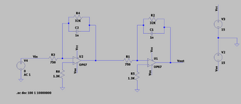
Hello,I have built the following two stage amplifier as shown bellow.
In open loop i get 63dB gain and BW about 3Khz.
when i tried to add a feedback resistor to lower the gain and increase the bandwidth as shown in the formula below i get no change at all.
two stage amplifier with feedback is shown in the end.
Where did i go wrong in implementing the feedback effect of feedback ressistor to lower the gain and increase the bandwidth?
Thanks.

1686934863192.png


1686934907757.png


1686935381039.png

1686935427232.png
 

Attachments

  • 1686934769707.png
    1686934769707.png
    17.2 KB · Views: 63
If you added a cap versus a R you would have a form of feed forward compensation,
but one would have to do the stability analysis.


Regards, Dana.
 
Hello danadakk, i have implemented the feedback shown bellow and got an increase of BW from 3K to 30K as shown bellow.
Is there some alternative OPAMP i can use to increase much more my BW?(to 5MHz)
Thanks.
1686985343256.png
1686985293972.png
 
Hi,

Is there some alternative OPAMP i can use to increase much more my BW?(to 5MHz)
I guess thousands.

Just use an OPAMP search for high GBW.
OPAMP search are provided by
* all OPAMP manufacturers
* almost all semiconductor distributors
* others

In case you don´t know about "GBW" do an internet search for "OPAMP GBW" (GBP, GBWP...)

Klaus
 
Hello Klauss, i have tried to change the OPAMP to a higher BW one its not changing at all the transfer function.
Could you please recommend me some material regarding higher BW OPAMP implementation?
Thanks.
 
Expectable because the bandwidth is limited by RC values rather than OP GBW. To achieve 5 MHz, a faster OP than 0.6 MHz OP07 is however required. I wonder what's the purpose of the 2 OP cascade circuit, is it a specific exercise? You can make your life easier by using a single OP of sufficient GBW, consider GBW factor 3-10 higher than intended closed loop gain * BW.
 
Hello, i Have used 350MHZ BW and it still doesnt work.
I want to make a two section cascode integrator with 5MHZ BW.
Is there some material or other configuration that could help?
Thanks.


1686997052115.png
 
I presume you are trying to do this :

1687006803265.png


Do you care if design is inverting or non inverting ?

Your spec of 5 Mhz implies G @ 5 Mhz = 0 db, thats correct ?

What -3db break are you willing to live with ?


Regards, Dana.
 
I want my design to be non inverting
i care about 5Mhzbandwidth more the the gain.
5Mhz =0dB correct
any other implementation?
 
If you dont like Zin consider a G = -1 inverting follower at input :

1687007450096.png


Note C2 is estimated stray C.


Regards, Dana.
 
Last edited:

    yefj

    Points: 2
    Helpful Answer Positive Rating
Hi,

Hello Klauss, i have tried to change the OPAMP to a higher BW one its not changing at all the transfer function.
Could you please recommend me some material regarding higher BW OPAMP implementation?
Thanks.
It's all confusing.

You say you want high bandwidth, but
* you use a slow OPAMP
* additionally you limit the bandwith by using the external Cs

You say you want integrator, but
* the circuit does not show an integrator at all

You say you want non inverting, but
* you use an inverting circuit ... then need two of them to get it non inverting

I have no clue want you really want.

Klaus
 
Note when you work with very fast OpAmps like this pay specific attention
to datasheet guidance on power supply bypassing at the OpAmp pins.


Regards, Dana.
--- Updated ---

Hi,


It's all confusing.

You say you want high bandwidth, but
* you use a slow OPAMP
* additionally you limit the bandwith by using the external Cs

You say you want integrator, but
* the circuit does not show an integrator at all

You say you want non inverting, but
* you use an inverting circuit ... then need two of them to get it non inverting

I have no clue want you really want.

Klaus
He went to a fast OpAmp in post #8.

Regards, Dana.
 
Hello Klauss, I have achieved my goal of increasing the BW.
I have a problem related to it if its ok i will post it in a new question.
1687010172002.png

1687010148480.png
 
Hello Klauss, I have achieved my goal of increasing the BW.
I have a problem related to it if its ok i will post it in a new question.
View attachment 183426
View attachment 183425

Thats not much of an integrator response with such high initial 3 db breakpoint.

Did you do a transient sim on it, with timestep somewhere around 10 nS ? To
do a gross check of stability. And I see you have no stray C elements at OpAmp
inputs. I see phase is crossing 180 with amp still showing G, and some peaking
in response curve, read stability will be of concern. Lastly your architecture is having
fdbk in a non inverting loop, another stability issue.


Regards, Dana.
 

LaTeX Commands Quick-Menu:

Similar threads

Part and Inventory Search

Welcome to EDABoard.com

Sponsor

Back
Top