Continue to Site

Welcome to EDAboard.com

Welcome to our site! EDAboard.com is an international Electronics Discussion Forum focused on EDA software, circuits, schematics, books, theory, papers, asic, pld, 8051, DSP, Network, RF, Analog Design, PCB, Service Manuals... and a whole lot more! To participate you need to register. Registration is free. Click here to register now.

PFC DC Bus Over-Voltage Protection

Status
Not open for further replies.

fethiyeli

Full Member level 4
Joined
Feb 9, 2013
Messages
207
Helped
10
Reputation
20
Reaction score
12
Trophy points
1,298
Activity points
2,986
Hi Everyone,

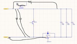
Due to over-voltages in ac mains, I need to protect the DC Bus, especially the PFC bulk capacitors. I did some research and here what I have found. Mosfet for over-voltage protection has been using for low power battery powered applications as I see. However, I have never seen any application doing the same thing for PFC.

And also by this method, I want to get rid of the by-pass relay parallel with NTC or PTC on ac mains.

We are also able to disconnect the power stage via the mosfet on DCBus- in order to decrease the stand-by current.

Is that kind of protection logical ? I know I need to sense the current, input voltage, etc. Via extra winding, inductor current can be taken.

I know there are lots of experienced guys here. That's why, I wanted to get your opinions. Thank you.

1632584281807.png
 
Last edited:

attached is the way to do this.
--- Updated ---

for input overcurrent protection, you can just rely on the input fuse.

I take it that you are protecting against high mains voltages due to eg "loss of neutral"?
..Because that FET that you place, will not be of much use against fast rising mains transients.
 

Attachments

  • fet protect.jpg
    fet protect.jpg
    201 KB · Views: 132
attached is the way to do this.
--- Updated ---

for input overcurrent protection, you can just rely on the input fuse.

I take it that you are protecting against high mains voltages due to eg "loss of neutral"?
..Because that FET that you place, will not be of much use against fast rising mains transients.

Hi, thank you for replying. I am thinking to design PFC output as about 400V. However, the place where the PFC will be used may have more than 265VRMS ac mains. It will not be used in Europe. Their ac mains is terrible as I heard. The PFC bulk capacitors are gonna have 500V rated.

For mains transient, I have varistors, capacitors etc. They are not shown here. This one is the example circuit of PFC.

It is gonna have zero cross circuit, so I was thinking to charge bulk capacitors by activating the mosfet at very small angle of ac mains during the falling time after the peak. There are some examples of this technique. It is obvious that it is gonna drawn peak currents but I think pre-charge diode will not be needed.

I just wanna ask why you added diode and cap across the DC bus.

Do you think that I need to put the mosfet on the left side of the IGBT ? I could not understand that one.
 
Yes i would not put the switch fet in the output rectifier loop of the boost pfc...since there is a high frequency spike of reverse recovery current** in this, and you wnat this loop as small_area as possible...so put the switch fet more upstream as shown. The cap is always needed.....its only small value, as you know if big value then you struggle to get good pfc.........the diode is for when you suddenly switch off the fet, and there is current flow in the inductor.......you cant break an inductive current...so the diode is there so it can freewheel the inductor current when fet switchs off....

The diode acorss the inductor is always needed in boost pfc......well, maybe not so much needed if you can garantee switching on the mains at the zero cross.......(but if you switch on mains with a realy at zero cross, remember with all the bouncing, there will not be a true zero_cross_switch_on).

Anyway, diode across L stops LC ringing with output caps, and stops overvoltage on caps as a consequence of this LC ringing. (it shorts out the inductor effectively)

** even if using sic, there is still a high current spike through the sic diode (when boost fet switchs on) due to its capacitance.

Thank you for your reply.

There was a cap actually before the inductor which was not shown in example schematic. Yea, I was thinking of freewheel diode. However, this solution again comes with diode. Fortunately, the diode before the inductor does not need to handle full load current. It needs to handle inductor back emf spike current. So, that diode does not need to connected to heat sink I guess.

Another concern I was thinking about is that how to drive n channel mosfet at dc bus. Since, the ground is at the right hand side of the mosfet, this mosfet can not be driven directly.

What kind of idea do you have for that ? I will simulate this circuit at PSIM or LTSpice.

I just want to get rid of relay and also have over-voltage protection for DC bus.

And also, n channel mosfet needs to handle more current than the PFC diode would need to handle.

1632604644589.png
 

you do have the bridge rectifier there of course, so the freewheel diode not so needed after all.

To turn on/off the fet, you could use a little isolated 12vout power module.....use its isolated output to drive the fet via a digital isolator, or optocoupler.
 

By the way, in your above diagram you have missed out the boost pfc diode, but i am sure you know this.
 

Status
Not open for further replies.

Similar threads

Part and Inventory Search

Welcome to EDABoard.com

Sponsor

Back
Top