Continue to Site

Welcome to EDAboard.com

Welcome to our site! EDAboard.com is an international Electronics Discussion Forum focused on EDA software, circuits, schematics, books, theory, papers, asic, pld, 8051, DSP, Network, RF, Analog Design, PCB, Service Manuals... and a whole lot more! To participate you need to register. Registration is free. Click here to register now.

Parallel switching psu

Status
Not open for further replies.

Dany_76*

Newbie
Joined
Oct 9, 2020
Messages
5
Helped
0
Reputation
0
Reaction score
0
Trophy points
1
Activity points
28
How to parallel switching power supply? Need schematic diagram
 

generally join the "+" to the "+" and the (-) to the (-) and hope the psu's have droop paralleling and current limit built in,

else you can put 0.22 ohms in each pos lead - going to the paralleling point - this is real world droop paralleling ....
 
generally join the "+" to the "+" and the (-) to the (-) and hope the psu's have droop paralleling and current limit built in,

else you can put 0.22 ohms in each pos lead - going to the paralleling point - this is real world droop paralleling ....
Hi easy peasy thx, but how if I am paralleling big current switching? I have 5 switching modul 30a each,to get 150a in total, do I need a big watt too in using a resistor for output to load?
 

what features do the power supplies have?
--- Updated ---

alternatively - use the same lengths of copper to connect to a common point - this will help current share if the output voltages are all set exactly the same ...
 

The aim is to create a voltage drop across each resistor. It should be the smallest amount necessary to make sure no power supply goes above 30A.

Greater voltage drop at the domineering supply. Least voltage drop at the underachiever.

It's hard to be sure what ohm value the resistors should be. Each time you try a different value it changes the distribution of current from all the power supplies.

Install diodes while experimenting, if you want to be certain no supply is forced into reverse current flow. Later you can remove the diodes.
 
what features do the power supplies have?
--- Updated ---

alternatively - use the same lengths of copper to connect to a common point - this will help current share if the output voltages are all set exactly the same ...
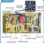
But I think for sett the same voltages it is difficult thing peasy, coz that can be different even milivolt fault. My modul have 12volt and 30a each, this i send you the image
 

Attachments

  • IMG_20200930_214053.jpg
    IMG_20200930_214053.jpg
    345.3 KB · Views: 86

The aim is to create a voltage drop across each resistor. It should be the smallest amount necessary to make sure no power supply goes above 30A.

Greater voltage drop at the domineering supply. Least voltage drop at the underachiever.

It's hard to be sure what ohm value the resistors should be. Each time you try a different value it changes the distribution of current from all the power supplies.

Install diodes while experimenting, if you want to be certain no supply is forced into reverse current flow. Later you can remove the diodes.
Hi brad thanks for ur detail answer, I will do experiment to get correct value of resistor in ohm/wattage
 

Hi,

There are supplies which are designed for paralleling.

One approach is that one acts as master while all others act as slave.
Then the master does it's regulation loop as usual and outputs it' current signal.
The slave take this current signal as setpoint input and regulate for the same current as the master.

With this, even adjustable voltage and current regulation is possible, while equal power distribution is guaranteed.

Klaus
 
0.005 ohms in each line would give 0.15 volts @ 4.5W each .... likely enough for reasonable paralleling
 
Status
Not open for further replies.

Similar threads

Part and Inventory Search

Welcome to EDABoard.com

Sponsor

Back
Top