Continue to Site

Welcome to EDAboard.com

Welcome to our site! EDAboard.com is an international Electronics Discussion Forum focused on EDA software, circuits, schematics, books, theory, papers, asic, pld, 8051, DSP, Network, RF, Analog Design, PCB, Service Manuals... and a whole lot more! To participate you need to register. Registration is free. Click here to register now.

HV PSU without any capacitor?

neazoi

Advanced Member level 6
Joined
Jan 5, 2008
Messages
4,122
Helped
13
Reputation
26
Reaction score
15
Trophy points
1,318
Location
Greece
Activity points
36,951
I have been experimenting with HV PSUs and I found that in a classic transformer - bridge rectifier PSU, one can remove the electrolytic filter capacitors if he includes a relatively large inductor after the bridge.

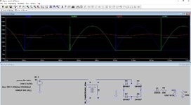
Here is my LTspice simulation, with the cyan line to represent the DC output.
I believe the inductor stores energy during the positive peaks and releases it during the low or zero voltage, thus providing the same action as that of a capacitor.

Is that the case or am I missing something?

If so, I wonder why companies like Tektronix and HP didn't use this simple technique and relied instead in electrolytics wich have EOL?
 

Attachments

  • amp11-AFTO4.zip
    854 bytes · Views: 50
  • Capture.JPG
    Capture.JPG
    153.5 KB · Views: 55
You describe a choke-input filter (smooth-er). Usually we see capacitive filtering because it's easier to work with.

Capacitive type tends to pull up waveforms at peak, producing maximum possible voltage with light load.

Choke filtering tends to average incoming waveforms, resulting in less power throughput (compared to capacitive). However a choke has the ability to affect the Ampere waveform drawn from the AC supply, its advantage being to smooth and reduce stress on the supply. The inductor presents impedance to incoming power, similar to the action of a buck (step-down) converter.

Capacitive filtering is associated with spike-y waveforms, and power factor error.
compare choke filter to capacitive filter.png


Click link to run above schematic in Falstad's animated interactive simulator (falstad.com/circuit):

tinyurl.com/yr7fdm2r

Click Toggle full screen (under File menu).
Drag mouse upward on scope area to enlarge scope traces.
 
Hi,

What I expect:
* on a capacitor: the lower the load current the lower the ripple voltage
* on a inductor: the lower the laod current the higher the ripple voltage

So you need a huge and expensive inductor to get low ripple voltage for a wide load current range.

I recommend to find out part cost for
* the expected output ripple voltage vs load current range (maybe 5%, 30%, 70%, 95% load current situations)

Klaus
 
Rectifiers with pure inductive filtering are the power engineering standard solution, review a text book in case of doubt. With 6, 12 or more phases used up to MW scale.

Also tube radio anode supply often used filter chokes, but combined with electrolytic cap.
 
Yes L/R= Tau But must more mullah ($) and bulk weight for 100 VA than Tau = RC
However for your design, the 5A 4H7 chokes are cheap. 1$~$3
1703691989605.png

The 100W 10R resistor is not too bad. ($)

But the 4000W 150V Zener is priceless ;) or the undersized one goes up in smoke with no load.

1703692208215.png
 
Last edited:
Last edited:

LaTeX Commands Quick-Menu:

Similar threads

Part and Inventory Search

Welcome to EDABoard.com

Sponsor

Back
Top