jomm
Newbie level 4

Follow along with the video below to see how to install our site as a web app on your home screen.
Note: This feature may not be available in some browsers.

Why don't you just use a diode in place of the lower mosfet, that will have the same effect (but will increase the voltage drop).
- - - Updated - - -
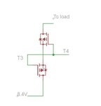
The sources of the two mosfets will have a voltage close to the power supply because of the diode in the lower mosfet, as soon as you apply a low voltage to the gate (gnd) then they both turn on (gate much lower than the source) if you apply about 8v to the gate then the gate voltage equals the voltage of the sources so the mosfets turn off.
Why don't you just use a diode in place of the lower mosfet, that will have the same effect (but will increase the voltage drop).
- - - Updated - - -
The sources of the two mosfets will have a voltage close to the power supply because of the diode in the lower mosfet, as soon as you apply a low voltage to the gate (gnd) then they both turn on (gate much lower than the source) if you apply about 8v to the gate then the gate voltage equals the voltage of the sources so the mosfets turn off.
The P mosfet turns on when the gate has a lower voltage compared to the source , both mosfets have their sources tied together and as long as the 8v supply is on the mosfet sources have 8v (almost) so when you apply a low voltage to the gated they both turn on
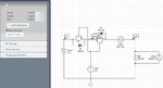
Your output is shorted to groung, there is no load so how can you see any voltage apart from 0v there?
") here is what i did .
here is what i did .
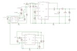
Yes, you could use a lower load that reflects the real circuit , I assume it consumes about 20 or 50ma so a resistor like 470ohm or lower would be more appropriate.