Welcome to our site! EDAboard.com is an international Electronics Discussion Forum focused on EDA software, circuits, schematics, books, theory, papers, asic, pld, 8051, DSP, Network, RF, Analog Design, PCB, Service Manuals... and a whole lot more! To participate you need to register. Registration is free. Click here to register now.
An optosensor typically contains a phototransistor. These are always manufactured as N-devices because of the singular effect of photons hitting the doped silicon. You can then add components to perform electronic tasks.
By feeding a signal through a transistor, you invert signal polarity (turn a high into a low, and a low into a high). Or if you wish to use an IC then an inverter gate is adequate.
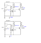
Here is one way to hook up an optocoupler. (I made one up from components because the simulator does not have an optocoupler in its library.)
Notice the transistor should be placed near 0V ground for greatest sensitivity. The resistors should be high enough ohm value so you don't get overmuch current going through the device. Yet the resistors should be low enough ohm value to allow proper operation.
- - - Updated - - -
The simulation is incorrect because the transistor ought to conduct when the led is On. Then the output voltage should be pulled low.
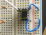
You should look how the connections on a breadboard connect together. You may be shorting everything out. If in doubt use a ohm meter to check. I suggest you place the opto over the center.
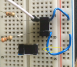
Thanks I did realise this yesterday, I was shorting out across the board.
Now I have it setting across the board but still not joy.
I think I need to work out the correct resistors, I've used 3k and 330 ohms like someone said but when I go direct to the output of the resistor I get no current out
What exactly are you trying to do? With this opto the light is interrupted by an object in the slot cutting the light beam. It should be very easy to get going.
Below shows you some voltages you can expect in the two states.
I have got a Opto switch, which I want to turn a motor off and on.
So when the switch is active the motor is on.
When the switch is deactive the motor is off.
I have this Opto switch
**broken link removed**
The switch keeps shorting out when I connect the output to my motor, one end of the motor is connected to ground and the other to the output of the switch.
The Ebay photo looks like an ordinary opto sensor. It probably contains a phototransistor. I doubt it is sufficiently robust to power a motor by itself.
I think it is meant to drive a second transistor. Do you have other transistors which are powerful enough to drive your motor, so that they will not burn up?
Post #11 has a schematic which could be adapted for your purposes. It has a 2N3904 transistor to drive a load, however that type is for light loads. You must drive the motor with a transistor which has the required ratings.
This site uses cookies to help personalise content, tailor your experience and to keep you logged in if you register.
By continuing to use this site, you are consenting to our use of cookies.

") needed.
needed.