Continue to Site

Welcome to EDAboard.com

Welcome to our site! EDAboard.com is an international Electronics Discussion Forum focused on EDA software, circuits, schematics, books, theory, papers, asic, pld, 8051, DSP, Network, RF, Analog Design, PCB, Service Manuals... and a whole lot more! To participate you need to register. Registration is free. Click here to register now.

operational amplifier problem

Status
Not open for further replies.
The way it's drawn, there is positive feedback so the output voltage will be either the maximum or minimum possible for the opamp. Maybe the opamp inputs should be swapped?
 

Maybe this is a trick question.

To solve it you need to know Vminout and Vmaxout for the opamp. These depend on the supply voltages. Depending in the supply voltages, there can be two solutions (like in a Schmitt Trigger circuit, due to the positive feedback).

For drawings/schematics/etc, you can best use .PNG as PNG is a lossless compression scheme.
 

There is a linear solution if the + and - inputs are swapped. Remember the op amp always tries to keep the + and - inputs at the same voltage. Here the + input is at +3V. There is +1V from the - input to the output. To get the - input to +3V, the output must be +2V. Again, the previous comment about having to swap the inputs is correct.

If the + and - inputs are not swapped, the output will go all the way positive or negative depending on which DC voltage comes up first. 3V first and the output goes all the way negative. 1V first and the output tries to go all the way positive. However, a positive output plus the 1V on the input may cause large input currents into the + input and other mischief.

BTW, putting a battery from the output to the - input is a way to make a reference voltage which has almost no drain on the battery. As a test, where is the + input connected? Why is there almost no current drain on the battery?
 
Last edited:
Vomin=-15 V
Vomax=+15 V
The inputs are not swapped; they are as in the picture;
I have runned a simulation(see picture)

If the inputs are as they are; Vo should be =Vomin ?[ -15 v]


Analog Ground: what do you mean by "depending on which DC voltage comes up first" ; "comes up" in what way?
This is a problem from a book; it is not a tested circuit;
 

Attachments

  • untitled2.bmp
    450.5 KB · Views: 54

I have runned a simulation(see picture)
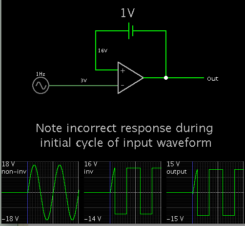
The solution exists only for an ideal OP without any bandwidth limitation, means it will be never observed with a real OP. There have been several previous threads about the paradox behaviour of ideal OP circuits with positive feedback.

It's however not clear if the original excercise problem is targetting to this solution, or if the real OP behaviour, latching either to positive or negative saturated output voltage is the expected solution.
 

An opamp has very high DC gain. So you can say:

when V+ > V-, Vout = +15V
When V+ < V-, Vout = -15V

I just make a guess let Vout = + 15V, what will be V+ and V-

V+ = 15+1V = 16V (I would not apply this to a real opamp with 15 V supply!!)
V- = -3V

So this is a stable situation as V+ > V- and that results in +15V output.

Now let we assume Vout = -15V

Now V+ = -14V and V- = 3V.

As V+ < V-, this is also a stable situation, Vout remains on -15V.

What stable state will apear in real world depends on the internals of the opamp and in which order and how fast all voltages reach their steady state value.

When for example the 3V is present before the opamp gets supply, the situation is that V+ < V- and that will result in Vout remaining 0V.

However when the supply voltage comes first (in time) then V+ > V- (as source "3V" was still 0 V), then Vout will be + 15V.
 

The output should be the same as the positive supply rail.

I recognize Falstad's simulator in the post #5 image. It has a glitch when modeling 100% hysteresis in an op amp.

I found that I must apply an input V which is beyond the min/max output figures. This causes correct output. Then reduce amplitude to a lesser value (3 V as shown).


The problem of latest posts #7 and #8 is that (similar to the original post) they don't specify which OP model should be assumed for the calculation respectively simulations.

If real OPs are considered, the answer to the question to which supply rail the output latches depends on many details. I doubt that it's of much practical relevance.
 
  • Like
Reactions: LvW

    LvW

    Points: 2
    Helpful Answer Positive Rating
I think the conclusion is the problem in the book has incorrect inputs. With the inputs switched, it is a good problem. Without the inputs switched, the problem makes no sense. We have had a good discussion about output saturation and some have fired up our simulators but, in the end, we are left with the error in the circuit diagram. IMHO. Any errata available for the text book?
 

Nobody noticed that the opamp is missing a power supply so it won't do a darn thing.
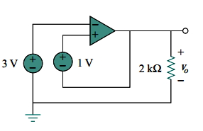
Just a matter of level of abstraction. You can simulate the problem with an "ideal" OP (e.g. infinite voltage swing). And as said, even get a finite solution with positive feedback if the OP has no bandwidth limitation.
 
The book says all op amps are ideal.
I found some others mistakes in the book; so it could be here another mistake.
 

Why the circuit can't be as shown (Meaning there is no error)?

From an educational standpoint it can be good. It triggers our grey cells. Now we have a discussion that what happens depends on (many) other factors and people can learn from it.

During classroom courses I also show examples where information is missing, or even contradicting, as you find that in real world also. I do this only in situations where I have direct contact with the attendees as I don't want them to waste time.
 

The only person who can resolve the "error or no error" issue is the author or the editor......
 

Status
Not open for further replies.

Similar threads

Part and Inventory Search

Welcome to EDABoard.com

Sponsor

Back
Top