Continue to Site

Welcome to EDAboard.com

Welcome to our site! EDAboard.com is an international Electronics Discussion Forum focused on EDA software, circuits, schematics, books, theory, papers, asic, pld, 8051, DSP, Network, RF, Analog Design, PCB, Service Manuals... and a whole lot more! To participate you need to register. Registration is free. Click here to register now.

operational amplifier circuit

Status
Not open for further replies.

electroboy

Member level 5
Joined
Dec 30, 2010
Messages
86
Helped
0
Reputation
0
Reaction score
0
Trophy points
1,286
Activity points
1,879
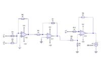
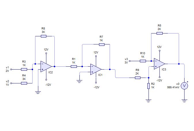
i have designed the following operational circuit with the help of you guys (thanks anyway) in such a way that i get an output of a*v1+b*v2-c*v3... where a,b,c are my desired ratios ..(for eg here: 3v1+v2-2v3) .. my question is " is there any way to simplify my circuit? "


Attachments

  • Capture2.JPG
    Capture2.JPG
    27.8 KB · Views: 72
Last edited:

A nice puzzle!
But is it the simplest?
Apologies if I'm missing something, but if the gain of the first stage (IC2) is increased and the gain of the second stage is also increased (Ic1), then V3 could be applied to the non-inverting input of the second stage (IC1), so that the 'subtraction' takes place there in the correct proportions. The output from IC1 may then be attenuated to return its combined outputs to the required levels.
 
I agree with keith. The given function can be realized with one opamp only.
Use the last stage and add one input via an additional resistor. Then, use the proper resistor values for adjusting the gain.
Unfortunately, some math is necessary.

---------- Post added at 21:57 ---------- Previous post was at 21:54 ----------

The calculation consists of a system of three equations for three unknown resistor ratios.
(Can be easily reduced to a system of two equations since the feedback ratio is fixed by the negative component)
 

Status
Not open for further replies.

Similar threads

Part and Inventory Search

Welcome to EDABoard.com

Sponsor

Back
Top