Welcome to our site! EDAboard.com is an international Electronics Discussion Forum focused on EDA software, circuits, schematics, books, theory, papers, asic, pld, 8051, DSP, Network, RF, Analog Design, PCB, Service Manuals... and a whole lot more! To participate you need to register. Registration is free. Click here to register now.
Hi
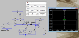
First, because the stimulus I1 is a DC value, I'll conveniently ignore the effect of C1.
V(n002) is then I1*(R2+[R1|R3])
In fact, it is approximately true we can ignore R1 and R3 then we have
V(n002) ~= I1*R2 = 1.144 V
This is so because of the 'golden rules': The op amp feedback keeps V- at zero, and essentially no current flows into the input pins.
Because R3<<R1, it is not worth finding the exact value of this parallel network, it will be 10 Ohms to within a very close tolerance - but also 10R << 71500 so the feedback at DC is about the same as R2 alone.
-----
Now for V(n007).
First, ignore R10 because it is directly across V1 and V1 does not care.
Then we can find the "Thevenin equivalent" circuit for V1 feeding R5 & R6, call...
Vn007, since no current (ideal OpAmp, or very very small) flows into the + input
of OpAmp we can ignore that. Also since R10 is in parallel with a V source we
can ignore that. So write a Thevinin loop starting with V1 all the way to Vn002 back
to ground and solve.
Hi
First, because the stimulus I1 is a DC value, I'll conveniently ignore the effect of C1.
V(n002) is then I1*(R2+[R1|R3])
In fact, it is approximately true we can ignore R1 and R3 then we have
V(n002) ~= I1*R2 = 1.144 V
This is so because of the 'golden rules': The op amp feedback keeps V- at zero, and essentially no current flows into the input pins.
Because R3<<R1, it is not worth finding the exact value of this parallel network, it will be 10 Ohms to within a very close tolerance - but also 10R << 71500 so the feedback at DC is about the same as R2 alone.
-----
Now for V(n007).
First, ignore R10 because it is directly across V1 and V1 does not care.
Then we can find the "Thevenin equivalent" circuit for V1 feeding R5 & R6, call this Veq
This is equivalent to a voltage Veq=(B.V1) with series resistance R5|R6.
It looks like this
GND---[Veq---Req]---v(n007)
Veq = 1.25*(215/(215+8.87))=1.20
Req = 8.52k
B is found from the potential divider equation: R6/(R6+R5) = 0.96
The equivent series resistance is R5|R6 because an ideal voltage source has no resistance. Thus current in or out of the divider R6/(R6+R5) sees a resistance R5|R6.
----
Now we tie n002 to n007 using R7:
This site uses cookies to help personalise content, tailor your experience and to keep you logged in if you register.
By continuing to use this site, you are consenting to our use of cookies.
")