Continue to Site

Welcome to EDAboard.com

Welcome to our site! EDAboard.com is an international Electronics Discussion Forum focused on EDA software, circuits, schematics, books, theory, papers, asic, pld, 8051, DSP, Network, RF, Analog Design, PCB, Service Manuals... and a whole lot more! To participate you need to register. Registration is free. Click here to register now.

one side of IR2110 full bridge mosfets burns instantly

Status
Not open for further replies.

farid72j

Junior Member level 3
Joined
Jul 29, 2021
Messages
26
Helped
0
Reputation
0
Reaction score
0
Trophy points
1
Activity points
208
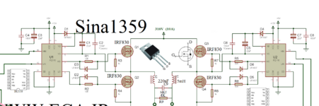
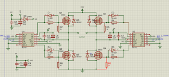
I have build a full bridge inverter using 2 IR2110 and 4 irf840 or 20n60 mosfets. pwm frequency of high side is 18 kHz and for the low side i use 50 Hz pulse. the circuit works fine with 25 and 50 volt from dc supply.
the problem is when i connect 310 v dc of rectifying 220 v ac to the circuit, 2 mosfet on one side burns instantly.

i use different mosfets and dead time up to 2 ms, the result is the same.
can someone tell me where is the problem?
thank you in advance.
 

Attachments

  • SinaInverterPureSineWave.png
    SinaInverterPureSineWave.png
    180.6 KB · Views: 354

The IRF840 Vishay worst case body diode is 2V max for threshold at 8A.

The UF4007 max is 1.7V at 1 A.

So its questionable if the UF4007 is dominant. But it is fast for sure at 75 nS at 1A.

You could set up a quick bench jig to test the presence and absence of the UF4007
by turnoff off L load on just one MOSFET switching the L load. To see what impact it
actually has. But better diode selection I would think is in order. Note this is a bit
of a crapshoot as body diodes are so poorly speced in datasheets to get a handle
on device to device variation.


Regards, Dana.
--- Updated ---


Yes on turnoff question.

Burnup when supply plugs in, sure sounds like a power sequencing issue in play here.
You could use a f() gen with ramp and a power pass transistor to ramp supply, and do
a scope capture triggered by say 2V to get an idea of whats going on in circuit. Scope
should have a deep enough memory to do it, depending on sampling rate you choose.


Regards, Dana.
Hi,

Both diodes should be fast at turn ON. This is not the problem.
The problem is turn OFF.

Reverse recovery time is...
Let´s assume there is reverse current through the MOSFET, thus the body diode becomes conductive.
But the problem is: it stays conductive for a short time even when voltage is reversed.

For a single low side or high side MOSFET this is not the problem, the dides usually never become conductive.

But in a half bridge...(example: Low side PWM while HIGH side is always OFF)
* let´s assume the LOW side is ON.
* then Low side is switched OFF
* due to some load side inductance the HIGH side MOSFET´s body diode becomes conductive
* if you now switch ON the LOW side MOSFET again, then you have the situation that the high side body diode stays conductive while the low side MOSFET is conductive too. --> very high current peak for a short time until the high side body diode releases.
(+supply --> high side diode (reverse) --> low side MOSFET --> GND)

Klaus
Ok, i will try the circuit with a bulb series with supply and removing filter from the output (only a resistor attached or nothing at all)

meanwhile can you guys explain why Vgs of high side drops after connecting even a low voltage supply?

thank you for your time.
 

Hi
can you guys explain why Vgs of high side drops after connecting even a low voltage supply?
Are you sure it is no measurement problem? How did you measure it?

Check your 12V supply.
Btw: with the 12V supply I miss at least one bulk capacitor and 1 fast ceramics capacitor for each IC.

Klaus
 

Hi

Are you sure it is no measurement problem? How did you measure it?

Check your 12V supply.
Btw: with the 12V supply I miss at least one bulk capacitor and 1 fast ceramics capacitor for each IC.

Klaus
couple of hours ago I've attached two picture of Vgs on oscilloscope before and after connecting mosfets supply.
both 5V and 12V supply has 22uf + 100nF capacitors.
 

Hi,

No capacitor is shown in 12V node in your schematic. Please update your schenatic.

You gave no information about measurement method .. nor 12V voltage (scope) , or eventual junction problems..


Klaus
 

Faulty parts or faulty / incorrect wiring up of the circuit - if you do not replace ALL the faulty parts the ckt will fail every time you power it.
--- Updated ---

do you understand de-coupling ?
 

Hi,

No capacitor is shown in 12V node in your schematic. Please update your schenatic.

You gave no information about measurement method .. nor 12V voltage (scope) , or eventual junction problems..


Klaus
here is the new schematic.
what do you mean by measurement method?
 

Attachments

  • Annotation 2021-08-03 022931.png
    Annotation 2021-08-03 022931.png
    80.3 KB · Views: 97

you need a nearby film / foil cap right on the H bridge across the 310VDC ...
--- Updated ---

Check all your gate drive resistors to see if any have blown open circuit ...
 

Probing - https://download.tek.com/document/55W_18412_9.pdf


Regards, Dana.
--- Updated ---

Hi,

Both diodes should be fast at turn ON. This is not the problem.
The problem is turn OFF.

Reverse recovery time is...
Let´s assume there is reverse current through the MOSFET, thus the body diode becomes conductive.
But the problem is: it stays conductive for a short time even when voltage is reversed.

For a single low side or high side MOSFET this is not the problem, the dides usually never become conductive.

But in a half bridge...(example: Low side PWM while HIGH side is always OFF)
* let´s assume the LOW side is ON.
* then Low side is switched OFF
* due to some load side inductance the HIGH side MOSFET´s body diode becomes conductive
* if you now switch ON the LOW side MOSFET again, then you have the situation that the high side body diode stays conductive while the low side MOSFET is conductive too. --> very high current peak for a short time until the high side body diode releases.
(+supply --> high side diode (reverse) --> low side MOSFET --> GND)

Klaus
Both Trr and Ton are problem issues in todays SMPS -


Covers turn on issue as well.


Regards, Dana.
--- Updated ---

Deeper explanation of Trr effects of body diode -

1627955398140.png


Regards, Dana.
 
Last edited:

Hi,

This nodes move 300V up and is not isolated from mains voltage, thys you can't use a usual scope and a usual scope probe.
Thus I ask how you measured it.

Klaus
the Vgs that i posted is at 24 V supply, so no problem.
but i measured 310 V dc with my scope before. i put the probe scale button on 10x and it worked fine.
--- Updated ---

Probing - https://download.tek.com/document/55W_18412_9.pdf


Regards, Dana.
--- Updated ---


Both Trr and Ton are problem issues in todays SMPS -


Covers turn on issue as well.


Regards, Dana.
--- Updated ---

Deeper explanation of Trr effects of body diode -

View attachment 171102

Regards, Dana.
i really dont think that diodes are the problem. cause i use 2ms dead time.
 

Hi,
you can't use a usual scope and a usual scope probe.
Thus I ask how you measured it.
You don´t do yourself a favour by giving vage informations.
But I don´t want to bother you by asking the same .. a third time...

Klaus
 

Hi,

You don´t do yourself a favour by giving vage informations.
But I don´t want to bother you by asking the same .. a third time...

Klaus
either i dont understand what do you mean or you dont understand what im saying.
thanks anyway
 

Hi,

* What exact scope are you using (especially inputs isolatated against earth GND?)
* What exact probes are you using
* Where exactly did you connect both probe connections. (PCB layout, photo..)
* Do you use any isolation transformer, if yes, where/how?

i really dont think that diodes are the problem. cause i use 2ms dead time.
If the diode current caused by the load or stray inductance lasts longer than 2ms (which is rather likely with motor as load or filter inductance) then even 2ms dead time is not enough.
In your case a 1A MOSFET current (= L1, L2 current) on a 2V voltage drop (diode + wiring + Ls) will keep current running for 5ms. More current --> more time.

Dead time is (in most cases) to avoid mosfet - mosfet cross conduction (not diode - mosfet)

Klaus
 

the Vgs that i posted is at 24 V supply, so no problem.
but i measured 310 V dc with my scope before. i put the probe scale button on 10x and it worked fine.
--- Updated ---


i really dont think that diodes are the problem. cause i use 2ms dead time.
Deadtime calculation -


Evidence is you are blowing gate oxide = excessive high V. Eg. the shorts you find when
testing blown MOSFETs.

Some intesting comments by IanMacDonald over at eevblog -


The probing comments in the ap note focused on isolation problems/protecting your scope
from blowing out its front end.

Here is a typical 10x probe spec -


Regards, Dana.
 
Last edited:

Hi,

* What exact scope are you using (especially inputs isolatated against earth GND?)
* What exact probes are you using
* Where exactly did you connect both probe connections. (PCB layout, photo..)
* Do you use any isolation transformer, if yes, where/how?


If the diode current caused by the load or stray inductance lasts longer than 2ms (which is rather likely with motor as load or filter inductance) then even 2ms dead time is not enough.
In your case a 1A MOSFET current (= L1, L2 current) on a 2V voltage drop (diode + wiring + Ls) will keep current running for 5ms. More current --> more time.

Dead time is (in most cases) to avoid mosfet - mosfet cross conduction (not diode - mosfet)

Klaus
im using gps-1102b (i think its channels are isolated from each other, not sure about isolation from ground).
my probes are GTP-060A-4
connected the probe on Rgs (photo attached)
no isolation used. just 4 optocoupler at the input signals. (ofcourse i didnt count transformers inside the power supplies.

i will test the circuit without motor and output filter to see if the inductance and diodes are the problem.
 

Attachments

  • 16279906051087671343395559100179.jpg
    16279906051087671343395559100179.jpg
    1 MB · Views: 81
  • 1627992542764350297714498104047.jpg
    1627992542764350297714498104047.jpg
    1 MB · Views: 66

Your scope has iso between channels, but shares a common ground amongst the channels.

1627994357583.png


Your board layout shows very poor ground system, and seems, for motor control,
to have very poor current handling capability. Lots of stray L and IR drop.


No heat sinks on the MOSFETs ? Thermal design.....


Regards, Dana.
 
Last edited:

Hi,
im using gps-1102b (i think its channels are isolated from each other, not sure about isolation from ground).
It takes 10 seconds to find the user manual.
It says:
Connect the Signal Wire Correctly
The potential of the signal wire is equal to the earth, so do not connect the signal
wire to a high voltage. Do not touch the exposed contacts or components.


So neither the channels are isolated for each other nor isolated form EARTH.

Be happy that nothing exploded and nothing burned so far.

*****
The PCB layout is not suitable for a switch mode supply.
Every critical path is to high impedance, mainly because of missing a good return path (GND plane).
* Missing 310V supply capacitors next to the MOSFETs
* fast ceramics capacitors need to be as close as possible to the IC´s supply pins. Bulk capacitors may be more far away (it´s the other way round on your PCB)

****
I strongly recommend
* to read scope manual,
* safety regulations
* application notes on how to design an SMPS PCB. (every SMPS IC manufacturer provides them. They have good reason for this! There also are thousands of discussions and example circuits in the internet, even videos)

Maybe you find it a waste of time, maybe you are in hurry ... but I still recommend to do first steps first.
It may need some time, but then you are able to create reliable designs.
Your design may work some hours, maybe some days, but I doubt it can reliably work for weeks.

Klaus
--- Updated ---

Hi,
Your scope has iso between channels, but shares a common ground amongst the channels.
No. This has nothing to do with electrical or safety isolation!
This is just channel to channel "crosstalk".

Klaus
 

Hi,

It takes 10 seconds to find the user manual.
It says:
Connect the Signal Wire Correctly
The potential of the signal wire is equal to the earth, so do not connect the signal
wire to a high voltage. Do not touch the exposed contacts or components.


So neither the channels are isolated for each other nor isolated form EARTH.

Be happy that nothing exploded and nothing burned so far.

*****
The PCB layout is not suitable for a switch mode supply.
Every critical path is to high impedance, mainly because of missing a good return path (GND plane).
* Missing 310V supply capacitors next to the MOSFETs
* fast ceramics capacitors need to be as close as possible to the IC´s supply pins. Bulk capacitors may be more far away (it´s the other way round on your PCB)

****
I strongly recommend
* to read scope manual,
* safety regulations
* application notes on how to design an SMPS PCB. (every SMPS IC manufacturer provides them. They have good reason for this! There also are thousands of discussions and example circuits in the internet, even videos)

Maybe you find it a waste of time, maybe you are in hurry ... but I still recommend to do first steps first.
It may need some time, but then you are able to create reliable designs.
Your design may work some hours, maybe some days, but I doubt it can reliably work for weeks.

Klaus
--- Updated ---

Hi,

No. This has nothing to do with electrical or safety isolation!
This is just channel to channel "crosstalk".

Klaus
Thats correct, the safety issue is a ground problem as prior discussed in ap note from tek posted.
And of course HV constraints, also discussed in that ap note.

Regards, Dana.
 

without a heat-sink attached - those fets are gonna go bang pretty quickly ....

also you cannot put a standard scope on the top fet - G-S or the radiation from earthing the flapping ( switching ) source will affect everything

make sure you are using ISOLATED probes - THESE ARE NOT STANDARD PROBES ...!

if you don't have isolated probes you need to measure 0v to gate and 0v to source and do the subtraction on the scope .....!

If your mains supply is not properly isolated you will have further issues ...! P.S A VARIAC DOES NOT GIVE ISOLATION. ..!
--- Updated ---

aLSO - you got no recoupling near the mosfets...! this is bad.
 

Status
Not open for further replies.

Part and Inventory Search

Welcome to EDABoard.com

Sponsor

Back
Top