Continue to Site

Welcome to EDAboard.com

Welcome to our site! EDAboard.com is an international Electronics Discussion Forum focused on EDA software, circuits, schematics, books, theory, papers, asic, pld, 8051, DSP, Network, RF, Analog Design, PCB, Service Manuals... and a whole lot more! To participate you need to register. Registration is free. Click here to register now.

Need help! Problem with 433 MHz video transmitter

Status
Not open for further replies.

qinqin

Newbie level 4
Newbie level 4
Joined
Aug 3, 2013
Messages
7
Helped
0
Reputation
0
Reaction score
0
Trophy points
1
Visit site
Activity points
52
Dear All,

I try to build a 433 MHz video transmitter to transmit TV signal. However, I always get strange modulation at 96-100MHz, never get 433 MHz modulation.

Would you please suggest what the reason could be and where have a circuit I can refer.

Thank you in advance.

Q
 

You can but without a practical UHF experience you may fail.
The inductor and capacitor values around the transistor should be halved at least. Instead of a coil a small wire loop can work at 433 MHz. My loop was 7-8 mm diameter and ~15 mm long. Many RF and even audio transistors can oscillate at 433 MHz.

Be ready to adjust base bias for good results.


Thank you jiripolivka.

Can I know which kind of transistor you can suggest. I cannot make the circuit oscillate at any frequency (except the unexpected 100MHz). Do you think it is because the transistor or just bad connection of the wires.

I am testing the circuit at breadboard now.

Q
 

Thank you jiripolivka.

Can I know which kind of transistor you can suggest. I cannot make the circuit oscillate at any frequency (except the unexpected 100MHz). Do you think it is because the transistor or just bad connection of the wires.

I am testing the circuit at breadboard now.

Q

I have used AF139 many years ago, now there are many better UHF transistors available. Even BC 348 can oscillate at >500 MHz. Connections must be shorter than 4-5 mm and I learned to check the oscillation conditions by measuring the collector current, by an analog 0-10 mA meter. If you touch the collector by your finger, collector current should drop from 8-10 to 2-3 mA.

At UHF, experience is important. Get ready and leArn by experiments!
 

Thank you jiripolivka.

Can I know which kind of transistor you can suggest. I cannot make the circuit oscillate at any frequency (except the unexpected 100MHz). Do you think it is because the transistor or just bad connection of the wires.

I am testing the circuit at breadboard now.

Q

433 MHz wouldn't work on breadboard..
RF is totally different than the others, please read something about that..
 

Try to find transistors from BFR series. BFR 90, 91, 92, 93. They are cheap, and still available in most places.
If the circuit has clean construction, with very short terminals and use solid ground (Manhattan style), can work even at few GHz.
 

433 MHz wouldn't work on breadboard..
RF is totally different than the others, please read something about that..

Thank you all for suggestions.

@BigBoss, if 433 MHz does not work on breadboard, is there an easy way to test the circuit and all the components.

Thanks.

Q
 

Thank you all for suggestions.

@BigBoss, if 433 MHz does not work on breadboard, is there an easy way to test the circuit and all the components.

Thanks.

Q

Yes..
Using double sided PCB will work at 433MHz.The vias that connect upper side and GND should be everywhere possible to decrease GND connections that are very important.
You don't need to order professional PCB, you can make it by yourself by drawing a proper PCB layout and you can also connect the vias by soldering short copper wires after drilled.
Search a little bit amateur radio fans' forums and internet, you will find very valuable information.


Hello Bigboss,

Is there a professional solid and flexible PCB print service you can suggest for this small size and quantity of PCB application.
And how to make my own PCB, can I use a blank prototyping board?

Thanks,
Q
 

Hello Bigboss,

Is there a professional solid and flexible PCB print service you can suggest for this small size and quantity of PCB application.
And how to make my own PCB, can I use a blank prototyping board?

Thanks,
Q

Which country?? There are many small quantity PCB manufacturer in Europe and I'm sure in US.But I don't know the other countries.
 

That is common base oscillator and with some impudence it possible make on prototyping board or what else, piece of glass with glued pads and so on. Probably it would be 3D structure, key word is SMD component ( transistor as max sot 23, capacitors 0603 ) with additional 1mm diameter wire loop, as wrote above and vu a la should work, with proper transistor ( BFR 360, AT-42086 and so on ) .
 

That is common base oscillator and with some impudence it possible make on prototyping board or what else, piece of glass with glued pads and so on. Probably it would be 3D structure, key word is SMD component ( transistor as max sot 23, capacitors 0603 ) with additional 1mm diameter wire loop, as wrote above and vu a la should work, with proper transistor ( BFR 360, AT-42086 and so on ) .


@Bob60, I am very intrested how to make SMD on piece of glass. Is there a tutorial.

@Bigboss, want to find a PCB print in US.

Thanks.
 

433MHz isn't THAT critical, as long as good construction practice is followed and wiring is kept short it can still be built using conventional components. You will probably find the coil becomes just a wire loop (a 'U' rather than having turns) but it should still work. I've prototyped at much higher frequencies than that using '3D' construction. Beware that you will not be licensed to transmit video on 433MHZ and you will cause interference to others and suffer it from others on that frequency.

Brian.
 

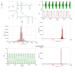
Here are some simulation results to show possible operation at 400 MHz using a common UHF transistor like suggested before.

Output level is quite low and may be increased by running it of a 12V supply or adding a suitable buffer amplifier.
 

Attachments

  • TV_TX.gif
    TV_TX.gif
    45.8 KB · Views: 128
Last edited:

Why not take apart an old VCR (Video Recorder) ?
Her you will find some interresting stuff like VHF-UHF modulator, tunable over a large range and video quality.
 

Why not take apart an old VCR (Video Recorder) ?
Her you will find some interresting stuff like VHF-UHF modulator, tunable over a large range and video quality.
Yes good idea. Especially on ebay possible to found something right and by the way check how looks 3D oscillator.
**broken link removed**
 

Status
Not open for further replies.

Part and Inventory Search

Welcome to EDABoard.com

Sponsor

Back
Top