Continue to Site

Welcome to EDAboard.com

Welcome to our site! EDAboard.com is an international Electronics Discussion Forum focused on EDA software, circuits, schematics, books, theory, papers, asic, pld, 8051, DSP, Network, RF, Analog Design, PCB, Service Manuals... and a whole lot more! To participate you need to register. Registration is free. Click here to register now.

433mHz Transmitter Range Problem

AlwiNOen

Newbie
Newbie level 4
Joined
Feb 26, 2023
Messages
5
Helped
0
Reputation
0
Reaction score
0
Trophy points
1
Activity points
32
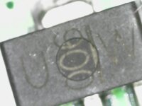
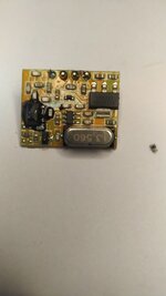
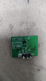
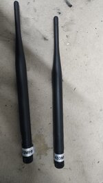
Hello. I have a circuit that uses a 433 MHz transceiver to transmit data remotely. The transmitter is powered by 12v and the transmitter has a 20cm long antenna. However, when I forget to attach an antenna, unfortunately the transmitter cannot be used at long range as before, possibly the transmitter is damaged. When this happens, unfortunately I have to change the circuit. because I can't find the same transmitter. I have attached pictures of the transmitter, do you think it is possible for me to fix this transmitter? Is there an item I should check or replace? Can you help me?

[MODERATOR ACTION] : Original post translated to English


WhatsApp Image 2023-02-26 at 22.58.52.jpeg
 

Attachments

  • WhatsApp Image 2023-02-26 at 22.58.52 (1).jpeg
    WhatsApp Image 2023-02-26 at 22.58.52 (1).jpeg
    86.8 KB · Views: 25
  • WhatsApp Image 2023-02-21 at 20.29.48.jpeg
    WhatsApp Image 2023-02-21 at 20.29.48.jpeg
    181.8 KB · Views: 25
  • WhatsApp Image 2023-02-26 at 23.11.47.jpeg
    WhatsApp Image 2023-02-26 at 23.11.47.jpeg
    201.7 KB · Views: 25
Last edited:

andre_luis

Super Moderator
Staff member
Advanced Member level 7
Joined
Nov 7, 2006
Messages
9,507
Helped
1,186
Reputation
2,391
Reaction score
1,186
Trophy points
1,403
Location
Brazil
Activity points
55,144
In transmission lines there is an effect called "reflection coefficient" which is strongly related to the geometry of the transmission line. For the 433MHz wavelenght the quarter of this is 17,31 cm and the round trip length would be even half that. You are perhaps facing to some issue on this regard. As a general rule of thumb for repairing boards handling power at some extent, check from the outside in, in this case, replacing the RF transistor first.
 

AlwiNOen

Newbie
Newbie level 4
Joined
Feb 26, 2023
Messages
5
Helped
0
Reputation
0
Reaction score
0
Trophy points
1
Activity points
32
In transmission lines there is an effect called "reflection coefficient" which is strongly related to the geometry of the transmission line. For the 433MHz wavelenght the quarter of this is 17,31 cm and the round trip length would be even half that. You are perhaps facing to some issue on this regard. As a general rule of thumb for repairing boards handling power at some extent, check from the outside in, in this case, replacing the RF transistor first.
Is it possible for you to show in the picture which product it is?
 

AlwiNOen

Newbie
Newbie level 4
Joined
Feb 26, 2023
Messages
5
Helped
0
Reputation
0
Reaction score
0
Trophy points
1
Activity points
32
You need to infer the schematic from the antenna inwards.
Like you said, probably the transistor is faulty, but I didn't get any results from what's written on it.
What can I do about it? How can I tell what kind of transistor it is?

1234.jpeg
 

Attachments

  • 123.jpeg
    123.jpeg
    31 KB · Views: 19

vfone

Advanced Member level 6
Joined
Oct 10, 2001
Messages
5,540
Helped
1,600
Reputation
3,205
Reaction score
1,203
Trophy points
1,393
Activity points
35,201
The output power of the transmitter is about +10dBm, and at this low power is unlikely to be damaged do to high VSWR. But never know..
The chip transmitter could be CYF115, or MICRF113 (marked OA9X9 in your circuit):

Check first if the LM1117-3.3 regulator have 3.3V at the output, and next check the crystal oscillator if is working. For these measurements you need a meter and an oscilloscope.
These modules are very cheap, and would be no big problem replacing them with newer ones.
 

AlwiNOen

Newbie
Newbie level 4
Joined
Feb 26, 2023
Messages
5
Helped
0
Reputation
0
Reaction score
0
Trophy points
1
Activity points
32
The output power of the transmitter is about +10dBm, and at this low power is unlikely to be damaged do to high VSWR. But never know..
The chip transmitter could be CYF115, or MICRF113 (marked OA9X9 in your circuit):

Check first if the LM1117-3.3 regulator have 3.3V at the output, and next check the crystal oscillator if is working. For these measurements you need a meter and an oscilloscope.
These modules are very cheap, and would be no big problem replacing them with newer ones.

There is nothing wrong with the LM1117-3.3 regulator, I measured it. But I don't have the oscilloscope.

Believe me, if I can find a product that I can use instead, I never want to deal with repair. However, this product is used in a boat and can broadcast from a distance of more than 300 meters up to the shore. If you have a product suggestion that I can use at this value, I would like to use it.
 
Last edited:

AlwiNOen

Newbie
Newbie level 4
Joined
Feb 26, 2023
Messages
5
Helped
0
Reputation
0
Reaction score
0
Trophy points
1
Activity points
32
I can't be certain but something like a BGA3018 is likely the damaged part.

Brian.
Thank you for your interest. But this product is not available in my country. So I need to make sure it's really him, because I can only get it from abroad..
 

LaTeX Commands Quick-Menu:

Similar threads

Part and Inventory Search

Welcome to EDABoard.com

Sponsor

Top