Continue to Site

Welcome to EDAboard.com

Welcome to our site! EDAboard.com is an international Electronics Discussion Forum focused on EDA software, circuits, schematics, books, theory, papers, asic, pld, 8051, DSP, Network, RF, Analog Design, PCB, Service Manuals... and a whole lot more! To participate you need to register. Registration is free. Click here to register now.

Need chip to withstand surges at input to power supply

Status
Not open for further replies.

cupoftea

Advanced Member level 5
Joined
Jun 13, 2021
Messages
2,632
Helped
54
Reputation
108
Reaction score
116
Trophy points
63
Activity points
13,799
Hi,
We are doing a Full Bridge, 10-36vin, 32vout, 300wout, 125kHz.
The input will see surges to MIL-STD-1275E and also DEF STAN 61-005 Part 6.

The LTC4364 is the beefiest of all offTheShelf surge protectors, but isnt capable of handling these standards' surges. Do you know of any that do, or are we looking at a home brew circuit only?

LTC4364

MIL-STD-1275E

DEF STAN 61-005 Part 6
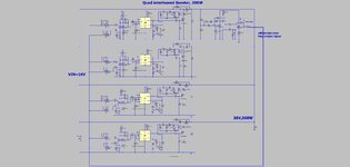
 

The alternative to the "Transistor farm" method, is the attached Quad interleaved Boost converter, which i reckon is more parts and cost than the "Transistor Farm" method. The quad boost would, AYK, go at the front end, and allow the Full bridge SMPS to be made from FETs rated to 200V, as discussed above kindly by contributors. Though do you agree, the Quad Boost front end is too expensive and too much complexity....compared to the albeit grungy linear_regulator_clamp_and_bypass_FETs, AKA, the "Transistor Farm" method.

(having said the above, i am wondering..."why dont they just put a big transient absorber on the bus???...eg, a dirty great resistor switched in and out by a IGBT or GTO"....)
 

Attachments

  • 4 x boost 300w.jpg
    4 x boost 300w.jpg
    183.3 KB · Views: 80
  • 4xBoost 300w.pdf
    227.9 KB · Views: 85
  • 4xBoost 300w.zip
    7.2 KB · Views: 79

surely a dual booster at 15A per stage would be fine, the FB only has to switch 8A, eliminating the series pass elements takes away a lot of heat.
 
Thanks,, yes i see your point, the Dual Booster looks good....with eg two of these low rdson , 200v FETs in pllel in each booster...(separate fet driver for each one)


The thing is, we want to use a PCB on a flat heatsink, (SMD FETs pass heat to heatsink via thermal vias to the heatsink) and so we will end up with more switching nodes over the heatsink, and thus more common mode EMC problems if we add these extra boosters....having said that, diode cathode is the heat tab, so thats not too bad....but the fet drain of the booster is going to be an unwanted common mode noise generator.
Dual boost will need custom inductors though, whereas quad could be done with say vishay offtheshelf ones. eg...
...these couldnt be used with Dual Boosters..and they are virtually the only high current offtheshelf inductors that have a core loss calculator.
I wish i could find a good , cheap InAmp to replace the Diff Amps in the Quad/Dual booster though.

..Though i must confess, when i start working through the "Transistor Farm" method, i think i am going to get overcrowded with circuitry needed to make all the parallel regulators share the current.
 
Last edited:

The biggest problem with the 38V front end boost solution, is that it doesnt shelter the full bridge from the 175vdc surge....so the diodes of that full bridge get really much bigger voltage referred to them during the surge.....which means much higher voltage diodes needed, with higher conduction loss.
 

Hence using properly sourced MBR20200CT for the o/p diodes ( for full bridge o/p ) - a great diode with a low EMI signature, low reverse Ipk and easy to snub, 2 in // for each booster diode will work very well too.
--- Updated ---

Remember 40V to 32V is a step down, so the o/p diodes will see ( at 175V in ) 140V for a full bridge of diodes

and 280V for a CT output. There are some good 300V diodes out there ( IXYS ) if you care to search.

If the Vout was 28V max then things look even better.
--- Updated ---

Also better to do your own boost chokes with RM6, 7, or 8 and good litz, the off the shelf parts will just cook ( don't say you weren't warned ).
 
Last edited:
Hi,
We are doing a Full Bridge, 10-36vin, 32vout, 300wout, 125kHz.
The input will see surges to MIL-STD-1275E and also DEF STAN 61-005 Part 6.

The LTC4364 is the beefiest of all offTheShelf surge protectors, but isnt capable of handling these standards' surges. Do you know of any that do, or are we looking at a home brew circuit only?

LTC4364

MIL-STD-1275E

DEF STAN 61-005 Part 6
How much of the specified surge will pass through the filter your proposing to use? I'm wondering if a 2 stage filter with bidirectional Transorb after the filter will be sufficient enough to protect the controller. I'm thinking something along the lines of 5.0SMDJ33CA https://www.littelfuse.com/media?re...lename=littelfuse-tvs-diode-5-0smdj-datasheet

If this would clamp the input voltage then it eleminates the issue and would maybe make for a less complex PSU.
 
Last edited:

@ scope-probe: the clamp power has been calc above - for 100mS it is far from trivial

a good filter - which are all LC based - can only smear out the impulse over time and thus reduce the peak height via this method - for the energies involved here the size of such a filter will be onerously large unfortunately - and would adversely affect the dynamics of the control of the following stages.
 
How much of the specified surge will pass through the filter your proposing to use?
Thanks, all of it....its quite a long term surge......up to 175VDC for 100ms. then tails down from there for the nxt 400ms...so the SMPS must still provide full load throughout this surge. This isnt really a surge we can clip, realistically.
The normal vin for the SMPS is 10-36VDC. -So you can see the challenge.


@ scope-probe: the clamp power has been calc above - for 100mS it is far from trivial

a good filter - which are all LC based - can only smear out the impulse over time and thus reduce the peak height via this method - for the energies involved here the size of such a filter will be onerously large unfortunately - and would adversely affect the dynamics of the control of the following stages.
Apologies i missed that.
 
1672355683111.png


This looks like the beastie ... a high temp MOV, intended for 8/20uS but ...

1672355750183.png


1672355797089.png


You can see the V20H60P rated for 100J, clamping to 175V at 100A, starting to clamp at 110VDC

4 of these will see 14A each and so should clamp to ~ 130VDC

Not a perfect solution but allows all components to be rated to 150VDC
--- Updated ---

This one even possibly better :

1672356154209.png


the V20H40P 135V @ 20A, 4 needed to give long term impulse resistance ( as MOV's wear out with every hit ). Also 140J each - so even better ...

56VDC stand off under normal operation.

Put these babies right at the input to guarantee < 135V down stream.

Also 4 x 6A10 diodes across the input to deal with any reverse spikes or batt connection.
 
Last edited:
Oops - 10A10 diode ( x 4 in // )


400A each for 8.3mS = enough to upset any external battery wires / fuses
--- Updated ---

@ scopeprobe - those solutions are fine until you have to carry 30A input at reasonably low losses ....
 

Last I looked at MOVs they still had two issues. One you note
is the sloppy threshold of breakdown. The other is, these are
not "indefinite repetition" devices, they degrade w/ repeated
"use" events. Meant more to prevent one catastrophe than make
a lifetime career out of so doing.

A P/N that doesn't suffer that, I expect would be proud to tell
you about cycle endurance @ level, I expect. Then you could
check cycle endurance against whether the threat spec calls
it "once and never again" or "anytime my crusty turret has to
rotate"....
 
Indeed - as written above in post #31 - MOV's do degrade with every hit - hence a good deal of oversizing is or can be used to extend the nominal life of the product - this also guarantees a reasonable clamp level below the worst case quoted in the data sheet.

These ones are 1000 cycle and high temp too - which helps a great deal.
 
Last edited:
Oops - 10A10 diode ( x 4 in // )


400A each for 8.3mS = enough to upset any external battery wires / fuses
--- Updated ---

@ scopeprobe - those solutions are fine until you have to carry 30A input at reasonably low losses ....

Not used them before unfortunately but some low RDS mosfets shouldn't give too much losses @ 30A
According to the datasheet RDSOn is approx 22mR @ 125DegC which is approx 600mW @ 30A which isn't too bad except perhaps a little sizable. https://www.mouser.co.uk/datasheet/2/427/sug90090e-1766349.pdf
 
@ scope probe:

0.022 ohm x 30^2 = 19.8 watts, so 5 devices needed to get to 4 watts overall, and then you need a high side gate drive for N type fets .... and level shifted control.
 

Not used them before unfortunately but some low RDS mosfets shouldn't give too much losses @ 30A
...Thanks, ill consider that for use as the "bypass FET". (or rather, many of them on pllel).
AYK, The other FET(s) are the regulator FET(s)...also pllel'd, but linear regs in pllel are a bit of a PITA as with what Easy Peasy kindly said just above....

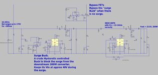
So therefore, we are now considering the "Surge Buck".......as follows....(attached LTspice and schem)
This is a Front End Buck, Hysteretic controlled, grotty-as-you-like....only works when the big surge hits...and gives a rough-as-you-like 40V to the 300W Full Bridge when the surge hits. When the surge isnt there, the Surge Buck is bypassed by a load of paralleled FETs.

Next problem is how to do the reverse polarity protection for this ?.....it must handle vin up to 175V, and input current flowing through it will be 33A max.....Hmm......shedload of back_to_back NFETs in pllel...?
 

Attachments

  • Surge Buck.jpg
    Surge Buck.jpg
    196.7 KB · Views: 69
  • Surge Buck.pdf
    184.8 KB · Views: 86
  • Surge Buck.zip
    3.5 KB · Views: 73
Last edited:

Sounds way too complex compared to the MOV's to limit to 135V abs max Vin, and then the booster designed to handle 135V - but boosting to 38 - 40V and then the down converter rated to 150V ( pwm reduce for Vin > 38V )

a lot less parts, a lot less heat, simpler hence more robust, less control, lower BOM, smaller, easier to make ....
 
Status
Not open for further replies.

Similar threads

Part and Inventory Search

Welcome to EDABoard.com

Sponsor

Back
Top