T3STY
Full Member level 4

- Joined
- Apr 17, 2012
- Messages
- 239
- Helped
- 24
- Reputation
- 48
- Reaction score
- 24
- Trophy points
- 1,308
- Activity points
- 3,715
need advice on pull-up pull-down switch circuit
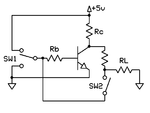
I need to design a circuit for a push button which, when pressed, should behave either as a pull-up or pull-down. So I though of a simple NPN -based circuit that simply swaps the V+ and GND lines across a pull-down circuit.

What happens is this: SW1 selects between 5V or GND. The transistor acts as a NOT gate. Between SW1 and the NOT output I have either [5V; GND] (pull-up) or [GND; 5V] (pull-down). The pull-up/down is formed then with the resistor-SW2 circuit. I have simulated the circuit in a circuit simulator, and it works.
However, I'd like to know from you if there are any alternative/better solutions to this? Can you identify any side-effects of this circuit or tell me why I should not use it?
I need to design a circuit for a push button which, when pressed, should behave either as a pull-up or pull-down. So I though of a simple NPN -based circuit that simply swaps the V+ and GND lines across a pull-down circuit.

What happens is this: SW1 selects between 5V or GND. The transistor acts as a NOT gate. Between SW1 and the NOT output I have either [5V; GND] (pull-up) or [GND; 5V] (pull-down). The pull-up/down is formed then with the resistor-SW2 circuit. I have simulated the circuit in a circuit simulator, and it works.
However, I'd like to know from you if there are any alternative/better solutions to this? Can you identify any side-effects of this circuit or tell me why I should not use it?


