Continue to Site

Welcome to EDAboard.com

Welcome to our site! EDAboard.com is an international Electronics Discussion Forum focused on EDA software, circuits, schematics, books, theory, papers, asic, pld, 8051, DSP, Network, RF, Analog Design, PCB, Service Manuals... and a whole lot more! To participate you need to register. Registration is free. Click here to register now.

Need advice for my toroidal core dimensions

treemon

Member level 3
Joined
Nov 2, 2022
Messages
60
Helped
0
Reputation
0
Reaction score
4
Trophy points
8
Activity points
402
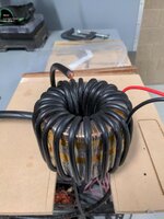
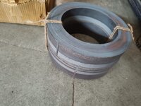
I am in need to build a 5kw inverter based on EGS002, for which I am first building a toroidal transformer, I got the toroidal core manufactured & delivered from a vendor.

Having no prior experience in doing this, I just used an android app called TransCalc to calculate core dimensions (and winding data), now I feel like core is bit awkward shape more like a ring.

My core dimensions are (mm)
OD=220
ID=150
Height=100

Weight 16kg
Material CRGO

I feel I had given too big ID, but I had to do because app told me to do so, large ID so large window area, which made core to transformer more power. According to calculation this can transfer almost 5kw..

Now I am little in dilemma whether to go ahead with this core, further put effort and also money on copper wires, already plenty of money is spent on core.

My main concern is, this look somewhat different from cores that companies are using in their inverter, should the core have a particular "form" for better efficiency, I mean the ratio of ID/OD/H must stick to some guideline?

I need suggestion from eda members, guide me whether if this core design is horribly wrong in that case I will not go ahead with this core, or if the core sizing s fine...please tell me.
 

Attachments

  • IMG-20230313-WA0002.jpg
    IMG-20230313-WA0002.jpg
    131 KB · Views: 182
anodized / oxidised / coloured - ask what the volt rating is ?
--- Updated ---

R = rho . L / A, x 1.31 for 100 deg C, 2,65mm dia = 5.51 mm^2 ( rho = 17E-9 for Cu )

600T is 102m or more ( likely 10% more ) on a single core => R100 = 0.412 ohms x 22^2 = 200 watts pri wire losses

which is why I suggested 2 x 2.24mm dia @ 500T only
 
Last edited:
Once the secondary is completed, you will then know two things for sure.
What sized hole is remaining, and the number of turns actually achieved in the secondary, it may of necessity end up a few turns short of the original goal.
I would not worry about planning the primary, until the secondary is fully completed.
That is a completely separate exercise.
--- Updated ---

You've said first (secondary) winding (230vac, 300turns) should be within 22mm ... Probably it is necessary for primary windings to stay near core and be able to impart maximum magnetic flux...
Sorry, forgot to reply to that.

One pass through the hole counts as one full turn, regardless of where in the hole that turn is.
Its normal practice to put on the thinnest wire first. That produces the flattest winding over which to wind the thicker wire.

If you put the thick wire on first, that produces a very lumpy winding which creates some real problems trying to fit a smooth layer of thinner wire over the top.

You will probably have noticed, mains powered (step down) transformers always have the primary wound on first, and the lower voltage secondary on top.

With an (inverter) step up transformers, its the other way around. The high voltage secondary goes on first, and the thicker primary goes over the top.

Electrically it makes no difference, but doing it that way creates far fewer problems in the winding process.

One other point not so far mentioned.
Its always best to space the wire so the wire is spread out evenly around the whole toroid. If you need one and a half layers, wind on one full layer, then add a second layer with half the turns spread out so it too goes all the way around the toroid. That produces a more evenly distributed magnetic field, lower leakage inductance than a lop sided layer that covers only half the core circumference.
 
Last edited:
That is very thick wire and difficult to handle, even with superhuman strength and the patience of a saint.
Yes, I am thinking, a 3mm Cu would be difficult to turn, and a 4mm AL would be even harder
Assuming two cores, you might like to think about using two strands of 1.8mm wire in parallel.
Yes, and maybe 3 or 4... If I dont get right size...

Your hole is so large, it might even be possible to wind on two strands of 1.8mm side by side together.
Quite a few different possibilities.
Maintaining a good/straight winding form would be challenging... neat approach is to wind with single thick wire, but again sourcing them and bending is difficult... I need to plan it

anodized / oxidised / coloured - ask what the volt rating is ?
Seller is non techie, he is a jewellery shop unfortunately... I will look for proper AL coating as you mentiioned.

Its normal practice to put on the thinnest wire first. That produces the flattest winding over which to wind the thicker wire.
This is what I planned, because secondary side once completed, cannot (need not) not be altered easily without unwinding primary, but LV side probably need to be changed later with thicker wire etc..so it has to be done later.
One other point not so far mentioned.
Its always best to space the wire so the wire is spread out evenly around the whole toroid. If you need one and a half layers, wind on one full layer, then add a second layer with half the turns spread out so it too goes all the way around the toroid. That produces a more evenly distributed magnetic field, lower leakage inductance than a lop sided layer that covers only half the core circumference.
Yes, agreed
 
The next step will probably be "the great wire hunt".
Once you actually have something, we can revisit the whole design and try to get a reasonable compromise.
Easy's suggestion of higher flux density and fewer turns is well worth considering too.
 
The next step will probably be "the great wire hunt".
Once you actually have something, we can revisit the whole design and try to get a reasonable compromise.
Easy's suggestion of higher flux density and fewer turns is well worth considering too.
Yes, and that.is not easy, when you are stuck in a third world country.

But if the core sourced, wires can also be sourced sooner or later, it just takes patience.

:cool:
 
Just to give you a better "feel" for selecting some suitable wire.

There is a formula for calculating the stiffness of steel coil springs.
If you look at that, you will find that stiffness increases by the FOURTH POWER of wire diameter.
A very slightly thicker wire increases the stiffness by an enormous amount.

There is a very narrow window for copper wire diameter that is both useful to us and tolerable to wind.
The thickest wire that is borderline user friendly would be 1.8mm diameter and will carry ten amps.
If you do have a choice, go for 1.8mm diameter.
Anything less than about 1.5mm diameter is really too thin.
Copper of 2.0mm or more is really nasty stuff to work with.
 
A very slightly thicker wire increases the stiffness by an enormous amount.
Umm... I see

Copper of 2.0mm or more is really nasty stuff to work with.
How about AL, If aluminium easier to bend than copper...

I am also exploring submersible pump winding wires, they have thick coating and it will be easier to source them.
 
This is why the hook winding towers are used by manufacturers of larger toroid based Cu-steel transformers,

they routinely wind up to 4mm dia without too many issues

We hand wind in the factory up to 2.24mm, often 4 or more in parallel - but there are jigs to assist.

Leaving copper aside and moving to Al:

Even if you could get the Al wire in an un-used state - winding such large wire areas will be an issue - Aluminium does not like being bent more than once.

Also you have not set out the low voltage winding current or voltage as yet .... ?
 
I have zero experience with aluminium wire, so cannot really comment.

Hand winding on a straight round conventional transformer bobbin is a lot easier than hand winding through the hole in a toroid.
I am sure large and powerful machinery can do wonderful things, including winding very thick wire through a small toroid. Doing it by hand, especially with used wire makes it a bit more difficult, especially if its a very first attempt.

When you have your wire I can give you a few hints on how to straighten it and make a large diameter "hoop" for winding a long continuous length of wire onto your toroid with least drama.

Low voltage winding is something we can look at later. At this stage obtaining wire and planning and winding a secondary will be enough to keep you fully occupied for quite some time.
 
Even if you could get the Al wire in an un-used state - winding such large wire areas will be an issue - Aluminium does not like being bent more than once.
Yes
Also you have not set out the low voltage winding current or voltage as yet .... ?
LV side windings will not be a challenge even with amount of large current, because turns are fewer and I think I can use any type of wire, they also need not be insulated, there will be large gaps between each turn.... There are many possibilities.
I have zero experience with aluminium wire, so cannot really comment.

Hand winding on a straight round conventional transformer bobbin is a lot easier than hand winding through the hole in a toroid.
I am sure large and powerful machinery can do wonderful things, including winding very thick wire through a small toroid. Doing it by hand, especially with used wire makes it a bit more difficult, especially if its a very first attempt.

When you have your wire I can give you a few hints on how to straighten it and make a large diameter "hoop" for winding a long continuous length of wire onto your toroid with least drama.

Low voltage winding is something we can look at later. At this stage obtaining wire and planning and winding a secondary will be enough to keep you fully occupied for quite some time.
Yes, problem is most sellers are not selling less than standard 21kg bundle, but if I visit any metro city then I will have options...

There is no good alibaba like market place here, in retail website like amazon etc they dont list lot of industrial items..

If one buys them online then the quality concern maybe there because so many copper brands exist of varying purity.

I do have 10meter, 2mm sample cu wire, and yeah they are very stiff..

Is it possible to use regular household copper wire for winding HV side? But they have thick insulation plastic with may inhibit electric field.
--- Updated ---

When you have your wire I can give you a few hints on how to straighten it and make a large diameter "hoop" for winding a long continuous length of wire onto your toroid with least drama.
Yes... That will be a great help
 
Regular household wire will probably have low temperature thermoplastic insulation. A current density of four amps per mm sq will run only slightly warm under average household loads, but at sustained 5Kw it will run pretty hot.
Not such a problem in the thick primary, because its on the outside, and the thick wire will have plenty of large air voids between and around turns.

The secondary will be closely wound in several layers, with much less opportunity for natural air cooling.

Here is a picture I found on the internet of a fairly typical home made inverter transformer using two stacked toroids, and plastic insulated battery cable used as a primary. Its quite normal practice.
The secondary really needs proper high temperature (200C) copper transformer wire.
 

Attachments

  • transformer.jpeg
    transformer.jpeg
    123.9 KB · Views: 79
sustained 5Kw it will run pretty hot.
Okay

The secondary will be closely wound in several layers, with much less opportunity for natural air cooling.
Yes, thats true...


Here is a picture I found on the internet of a fairly typical home made inverter transformer using two stacked toroids, and plastic insulated battery cable used as a primary. Its quite normal practice.
The secondary really needs proper high temperature (200C) copper transformer wire.
Thats what I planned to do with primary, after I seen these type of windings are frequently found in large ferrite inductors..
--- Updated ---

Leaving copper aside and moving to Al:

If you check above link, 3.5mm AL wire, it seem to have varnish layer... But I am not fully confident how good is insulation. Problem is I have to go with what is available.... Or wait long ...
 
Last edited:
That Bonsai wire "for home and garden" is structural wire, and I am sure it is very stiff and strong too !
I would place little faith in the insulation properties of that.
Sorry, but I just cannot raise any enthusiasm at all for aluminium wire.
I suppose you could always request a sample.
 
Also - that AL wire will not be 99.85 % pure and will work harden even worse that good AL wdg wire

as above - a tiny nick or scratch during wdg could cause a shorted turn
 
That Bonsai wire "for home and garden" is structural wire, and I am sure it is very stiff and strong too !
I would place little faith in the insulation properties of that.
Sorry, but I just cannot raise any enthusiasm at all for aluminium wire.
I suppose you could always request a sample.
Okay... Then maybe I go with standard 21 kg copper spool, I am up for stockpiling industrial metals for future needs, specially when currency is depreciating, but what else use can be there for a 1.8/2mm copper wire, I can utilize no more than 6kg in my transformer.
--- Updated ---

Also - that AL wire will not be 99.85 % pure and will work harden even worse that good AL wdg wire

as above - a tiny nick or scratch during wdg could cause a shorted turn
Okay... So basically thick AL wires are risky as coating could torn when bending them, its due to too much stress in that area...specially with thick wire.
 
Last edited:
There must surely be companies in India winding transformers, or rewinding generators, alternators, and motors.
You might be able to do a deal.
How about copper wire from China ?

I think you might regret trying to wind anything thicker than 1.8mm by hand.
 
There must surely be companies in India winding transformers, or rewinding generators, alternators, and motors.
You might be able to do a deal.
How about copper wire from China ?

Usually motor windings motors do not have more than 1mm, for example 1hp submersible pump they are using 1mm copper. Many Chinese websites are banned in India, there are few known trusted brands for copper but when you are ordering from china thats not the case.

Before this inverter I had an inverter of chinese make cnswipower, 1500w high frequency type, within an year of use, interver failed, and failure was catastrophic across so many components including spwm driver not just mosfet, I could never repair it.

Then I decided to build my own...

I think you might regret trying to wind anything thicker than 1.8mm by hand.
Yes, Actually I have a sample 2mm copper wire and its very hard.

One seller who is selling 21kg spool said his Brand is "bentex" an imported brand, have you heard of it?
 

LaTeX Commands Quick-Menu:

Similar threads

Part and Inventory Search

Welcome to EDABoard.com

Sponsor

Back
Top