Continue to Site

Welcome to EDAboard.com

Welcome to our site! EDAboard.com is an international Electronics Discussion Forum focused on EDA software, circuits, schematics, books, theory, papers, asic, pld, 8051, DSP, Network, RF, Analog Design, PCB, Service Manuals... and a whole lot more! To participate you need to register. Registration is free. Click here to register now.

Need advice for my toroidal core dimensions

treemon

Member level 3
Joined
Nov 2, 2022
Messages
60
Helped
0
Reputation
0
Reaction score
4
Trophy points
8
Activity points
402
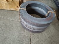
I am in need to build a 5kw inverter based on EGS002, for which I am first building a toroidal transformer, I got the toroidal core manufactured & delivered from a vendor.

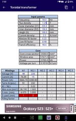
Having no prior experience in doing this, I just used an android app called TransCalc to calculate core dimensions (and winding data), now I feel like core is bit awkward shape more like a ring.

My core dimensions are (mm)
OD=220
ID=150
Height=100

Weight 16kg
Material CRGO

I feel I had given too big ID, but I had to do because app told me to do so, large ID so large window area, which made core to transformer more power. According to calculation this can transfer almost 5kw..

Now I am little in dilemma whether to go ahead with this core, further put effort and also money on copper wires, already plenty of money is spent on core.

My main concern is, this look somewhat different from cores that companies are using in their inverter, should the core have a particular "form" for better efficiency, I mean the ratio of ID/OD/H must stick to some guideline?

I need suggestion from eda members, guide me whether if this core design is horribly wrong in that case I will not go ahead with this core, or if the core sizing s fine...please tell me.
 

Attachments

  • IMG-20230313-WA0002.jpg
    IMG-20230313-WA0002.jpg
    131 KB · Views: 146
lots of tape to protect the wires from the core edges

Bpk = Erms / ( 4.44 F N Ae ) for sine wave voltage sources applied

Bpk @ 50Hz should be 1.25 T say, thus for 230Vac, 50Hz,

the product of N . Ae = 0.829

So for 12 x 5 cm ( 6000 mm ^2 ) N = 138 Turns ( 6000 mm^2 = 6000E-6 m^2 )
 
lots of tape to protect the wires from the core edges


Bpk = Erms / ( 4.44 F N Ae ) for sine wave voltage sources applied


Bpk @ 50Hz should be 1.25 T say, thus for 230Vac, 50Hz,


the product of N . Ae = 0.829


So for 12 x 5 cm ( 6000 mm ^2 ) N = 138 Turns ( 6000 mm^2 = 6000E-6 m^2 )

@@@@@@@@@@@@@@@@
Ok thanks for those info, I am thinking to first grind the corners to round off the edges and then apply tapes

so I can use 1.25T instead of 1T ? Below is the calculation from TransCalc is not in line with what you given (image)


Also what about correctedness of core "form" ? Should I go ahead with this core?
My reply is merged with quoted lines, please look below @@@@@@
 

Attachments

  • Screenshot_2023-03-28-07-33-01-750.jpeg
    Screenshot_2023-03-28-07-33-01-750.jpeg
    333.3 KB · Views: 139
The core area appears to be 70mm x 100mm - so a little larger than my guess

1T implies the core material is a bit on the crappy side

I'm not too interested if you think some unknown spread sheet is more accurate than the standard formula.
--- Updated ---

It is entirely up to you if you wish to go ahead - if you can find the wire - it should just fit for 5kW ( 22A, 230Vac ) _ LV pri.

the core losses are unknown as you do not appear to have any data on the core
--- Updated ---

By the way, 70mm OD-ID x 100mm high = 7000 mm^2

your screen shot shows 3500mm^2

so that appears to be wrong right off the bat.
This is an android app called TransCalc not spreadsheet, He has also given all the formulae used inside.

I will crosscheck with any example data on Google, match them with what TransCalc gives.

Core material as mentioned CRGO steel.

I think app takes only one side of ring as core cross section, which will be half of 7000.

I still need any final word on my core design, will it be efficient? Or its big ID will have any side effects?

For example if we keeping core cross same and vary ID from too small to very large.. Then what is the effect on transformer working.
 
" I think app takes only one side of ring as core cross section, which will be half of 7000. "

OK - was thinking Router - R inner
--- Updated ---

Cold Rolled Grain Oriented is not really a definition that allows core losses to be estimated - there are loads of Si blends and thicknesses and process variations - 0.35mm 4% Si would be a low loss type of material.
Ok,

What is your view on large ID, is that going to impact efficiency?

Also its core cross section is a steep rectangle (100mm tall), I could have made it near square...but now it cannot be changed.

Do these things make any impact?
 
For a domestic inverter application, the average power output over 24 hours might be quite low, seeing 5Kw peaks only intermittently. What is critical for overall efficiency is core loss and inverter no load idling current. Over 24 hours, that can add up to be an appreciable fraction of total daily inverter power.

So the first thing I would do with an unknown core is measure the magnetizing current versus turns per volt to arrive at a suitable design flux density.

Pretty easy to do, just wind a test coil onto the core of any old wire, maybe 20 or 50 turns, it does not really matter. Hook that up to a variac, and measure the applied voltage and the current it produces. For a 5Kw core, something in the range of 20 Va to 30Va at one Tesla might be a reasonable guess. It will be a lot higher than that at 1.25 Tesla.

So you decide on a suitable design operating flux density.
If you go low, maybe one Tesla, inverter idling current will be low, but the transformer will require more turns, which requires thinner wire, and that creates a higher temperature rise, and a lower continuous final power rating.

A higher flux density will enable a higher power rating, but the inverter idling current will become much greater. One Tesla, or something close to that is usually a pretty good compromise for a domestic inverter application.

Commercial transformers always run at much higher flux densities than that, it gives a higher power rating, better voltage regulation, for less copper and steel used. A more financially efficient transformer maybe, but less than ideal for an inverter that runs at relatively low power most of the time.

Once you have decided on the operating turns per volt (and flux density), its fairly straightforward to work out the primary and secondary turns required.
 
Last edited:
Do know the strip thickness of your toroid ?

In the picture you show two toroids one atop the other, is this so for your case ?

As you say you have received the core already you are limited in options - measuring the VA for a test wdg above is a good start to the design process.
 
Do not be concerned about the larger than usual hole size, in fact it will be a positive advantage when doing the actual winding.
It just means that slightly more copper may be required to fill the hole than might otherwise be the case.

There is probably a theoretically optimum core geometry, taking into account the relative cost of the toroid and the cost of the copper wire. If you were mass producing these by the thousands, saving a coupe of dollars on each one starts to add up.
Commercial toroid cross sectional dimensions vary significantly between suppliers, there are no accepted industry standard sizes or shapes as with stamped E and I laminations.

Just winding one transformer at home for yourself, its really not something to get stressed out over.
What you already have will be fine.
Thank you so much, now I have got some confidence over this project, I will follow the tests/steps you recommended in earlier thread.

Highly appreciate the inputs from kind members of edaboard, otherwise a newbie would be lost.
--- Updated ---

Do know the strip thickness of your toroid ?

In the picture you show two toroids one atop the other, is this so for your case ?

As you say you have received the core already you are limited in options - measuring the VA for a test wdg above is a good start to the design process.
Strip thickness is 50mm, you are right, vendor didnt had 100mm stripe so he made two, and I am thinking to combine them with glue.

That may or may not create buzzing noise, but it should reduce eddy current, do you see any side effect, with two cores stacked together?
 
Last edited:
50mm or 0.5mm ?

I am enquiring about the thickness of the strip ?
--- Updated ---

Obviously a square cross section minimises the mean length of turn - reducing the copper needed

In larger power transformers ( 3 phase E type ) steel is added to made a rounder cross section just for this reason - i.e. maximal steel - minimum copper to meet spec.
I see, strip thickness is 0.5 mm
 
Glue will be fine.

Many people have difficulty sourcing the larger sized toroids secondhand, usually scrounged from dead scrapped grid tie inverters that have blown up. Often these are unrepairable, for varios reasons, but the cores can definitely be recycled.
Stacking cores is a perfectly acceptable technique for increasing the power level.
Its done all the time for home built inverters here in Australia.

Once you have some real world test results for magnetizing VA, we can move on further from there.
Ok, thanks...

I have painted it, to avoid corrosion, I will be posting VA test result here, Luckily I do have a variastor circuit which I can utilize.

:)
 
Yup,
A single toroidal winding, with a continuously adjustable tapping.
 

Attachments

  • variac1.jpeg
    variac1.jpeg
    13.7 KB · Views: 80
  • variac2.png
    variac2.png
    4.1 KB · Views: 73
  • variac3.jpeg
    variac3.jpeg
    9.3 KB · Views: 75
  • variac4.jpeg
    variac4.jpeg
    9.4 KB · Views: 70
variac = variable auto transformer - usually another toroid with wdgs and a sliding contact ...
Ok, then that variac is something out of my reach currently, actually I wanted to say I have "thyristor voltage regulator", can I use this to limit current?
--- Updated ---

Yup,
A single toroidal winding, with a continuously adjustable tapping.
Variac I dont have, but I have a 220 VAC to 50VAC step down transformer, If i hook this then, can idle current can be measured with a reduced voltage?
 
O/k, there is another less convenient way to go about all this.

Start by winding a test coil on your toroid of about 1.3 turns per volt.
If your transformer is 50 volts, try perhaps 65 turns to begin with.
That should produce close to 1 Tesla at 50 Hz.
Measure the applied voltage (50v) and the current in the test winding.
A rough as guts wild guess might be in the region of 500mA to 1 amp. (25 VA to 50 VA measured)

Try more measurements using a very slightly different turns count.
The voltage probably will not change very much, but the measured current certainly will.
 
Last edited:

LaTeX Commands Quick-Menu:

Similar threads

Part and Inventory Search

Welcome to EDABoard.com

Sponsor

Back
Top