Continue to Site

Welcome to EDAboard.com

Welcome to our site! EDAboard.com is an international Electronics Discussion Forum focused on EDA software, circuits, schematics, books, theory, papers, asic, pld, 8051, DSP, Network, RF, Analog Design, PCB, Service Manuals... and a whole lot more! To participate you need to register. Registration is free. Click here to register now.

Need Advice for High Current, High Voltage, High Speed, Switching

townsend

Member level 1
Joined
May 19, 2023
Messages
32
Helped
0
Reputation
0
Reaction score
1
Trophy points
6
Activity points
417
Hello everyone!

I'm new here - just freshly registered. I have a PhD in Neuroscience, with other degrees prior in Mathematics and Computer Science, and prior to that I earned diplomas from college in the areas of Electronics and Electrical. I don't profess to be a formally recognized "Engineer" and do not have the PEng designation, but my formal study of the area at the college level was carried through as I worked on my Undergrad, Master's and Phd, and I do have two patents registered to my name in the area of EEG acquisition electronics.

Put simply, I might not be familiar with all the jargon that PEng's use, but I have a good grasp of the principles and am able to design my own stuff and debug/troubleshoot other peoples' designs. So, please excuse me in advance if I don't seem to follow what you are saying - its just a matter of us speaking different working languages.

So, here's my question:
I am in the middle of trying to implement an idea, but I'll spare you all the details and only include what is necessary to help describe my problem. I have a system operating at about 680V and about 40A, and I need to be able to switch a component in and out about 120 times per second. I am under the gun to get a prototype completed fast, and so instead of working on my own switching mechanism, I chose to use a solid state relay (SSR). I chose one with random on/off (i.e. it doesn't wait for a zero crossing, but switches when you tell it to). I also need optical isolation to simplify the connection to the microcontroller that will be handling the timing.

To guarantee perfect operation, I really need sub-millisecond timing accuracy. I also don't want to break the bank with the project, so I wanted to keep the cost of the switch under $50. Unfortunately, the only solution that I found indicated in the datasheet that the device would switch on (and off) within 1 millisecond of being told to do so.

I was disappointed but checked my calculations and found that although not ideal, this would produce "acceptable" results. Without providing all the details, the potential for the delay will result in the output voltage of my project being generated to be a little higher or lower than desired, but still within acceptable limits.

1/ Can anyone point me to a SSR that can respond within 100usec, is within budget, and meets the voltage and current requirements?
2/ Can anyone point me to a resource to help me design my own switching system so I don't need to use a ready-made SSR?

Regarding question 2 above, I specialize in low current low voltage analog and digital applications, so "power electronics" is not a familiar area for me. That's why I'm here seeking some advice. Thanks in advance!
-gt-
 
Hi,

AC or DC?
Since you talk about zero crossing I guess it´s AC, but can´t be sure. So please tell us the wavefrom.

What is 680V? Peak, average, RMS?
Same for the current.

My first idea: An IGBT controlled with an optocoupler.
Many applications already available. Documents, discussions, evaluation boards...

Klaus
 
So its 680V DC, and you want to switch in a 40A load?
I would just use parallel FETs.
Can you say what the load is?
Your switching frequency is 120Hz....what is your duty cycle?
(sorry Klaus you must have answered same time as me)
 
Thanks for the quick responses from both of you.

The application is in the middle of a rectifier circuit between AC and DC, so I'm not sure how to answer that question, but I suppose it doesn't matter, since regardless of the voltage or the change in voltage or the polarity, I need to switch at an arbitrary point in time. However, I think I can still answer the question in the following way: Current will always flow in the same direction in the switched path. Does that help? So the current is between 0 and 40 amps in the same direction always.

Everything is based on peak, not RMS nor average parameters.

The duty cycle is about 50% more or less.

Did that cover everything?
-gt-
 
Actually, the component being switched is a capacitor and will have TWO such switching devices to change ONE of it's legs between two different points in the circuit. The other leg remains fixed. I mention that because the 50% of the time is connected to charge, the current won't be 40 amps for the entire charge cycle. When that switch drops out and the other switch kicks in, it will be in a discharge cycle for the other 50% of the time, but again it won't be dumping 40A the whole discharge cycle. Therefore the "duty cycle" is probably effectively less than 50% for each of the two switches.

If both switches were closed at the same time, there'd be a problem. But the switchover from one to the other is not critical, so they can both be off for some safety "gap" time. Probably much more detail than you need, but since one of you asked specifically about duty cycle, I wanted to answer it fully.
-gt-
 
This is a side question: I'm assuming that the very small inductance and resistance in the wires is going to be sufficient to prevent the theoretical inrush of an otherwise infinite current, and that however high such current is in reality, it will not damage the switching device. Do you think that's a safe bet? I'm reminded when a physicist looked at one of my schematics and said I needed a resistor between the rectifier and a filter cap or the current would be infinite and burn out the circuit. In practice, there seems to be no major concern about this and I suspect it is because the wire is not a perfect conductor but already has enough (albeit a very small amount) of inductance and resistance to eliminate such catastrophes. Having been a service technician in the early 80's, I never serviced a power supply where the design actually included such current limiting components. What is your take on this?

This is related to this thread in that I do not currently have anything in my design to address this issue if it really is an issue. So I thought I should ask.
-gt-
 
SSRs tend to be slow. You ought to back up a couple of steps
and look at the source, signal and load to see whether you
require things that only a SSR (or an even more specific kind
of SSR) can do, or it there's a simpler and faster solution.

120Hz is not high speed. For that kind of voltage you ought
to be able to toggle > 1MHz. Might look at isolated FET drivers
if your signal is unipolar, these can be had with > 1kV isolation
and double digit nanosecond prop delays.
 
Thanks for your feedback.

You're right - I guess I should have described my requirement as "low delay" rather than "high speed". Usually they go hand in hand, so I just said "high speed". My actually requirement is that within 100 usec of being asked to come on or to go off, the device needs to respond.

As I mentioned, I chose an SSR to get a prototype up and running quickly. Its a ready-to-go solution with only 4 connections. That was my main motivation for using an SSR. No thinking, no wiring, just plug-and-play. It was also pretty cheap. The only drawback is that it takes 10 times longer to respond than I'd like. I was hoping someone might know of an SSR with a lower delay which still satisfied the other requirements, especially price.
-gt-
 
So its 680V DC, and you want to switch in a 40A load?
I would just use parallel FETs.
Can you say what the load is?
Your switching frequency is 120Hz....what is your duty cycle?
(sorry Klaus you must have answered same time as me)
Why parallel FETs if it's DC?
To answer your question, the load is a capacitor and will actually have TWO such switches. One to charge it, and another to discharge it. Although the current reverses during this process at the capacitor, each switch only has current passing through it in ONE direction.
-gt-
 
Hi,

AC or DC?
Since you talk about zero crossing I guess it´s AC, but can´t be sure. So please tell us the wavefrom.

What is 680V? Peak, average, RMS?
Same for the current.

My first idea: An IGBT controlled with an optocoupler.
Many applications already available. Documents, discussions, evaluation boards...

Klaus
I like the idea of an IGBT, especially with an optocoupler. Can you point me to some examples online?
 
Hi,

some new information from your side: capacitor.
A capacitor is rather difficult to "switch". It´s because it is very low ohmic for fast voltage change. So from OFF to ON there may be a huge current. The current is determeined by:
* the voltage difference (capacitor_voltage - source_voltage)
* and by the series impedance: source impedance, switch impedance, capacitor ESR, wiring..)
The current may be short, but may be destructive. Swithing ON a capacitor - without a dominating series inductance - is always combined with (huge) power dissipation.

Math: If I´m not mistaken .. switching ON a capacitor (no series inductance) causes the same amount of energy dissipated (in switch, wiring, ...) than it is stored in the capacitor: W = 0.5 x V x V x C.
The overall efficiency is 0.5 or 50%.

****
Some timing information at electonic switches:
There is the control signal and the load signal.
Each control signal has it´s definitions (levels) when it is ON and OFF. (for TTL signals this may be 2.0V and 0.8V)
The same is true for the load signal. In your case the ON/OFF state may be defined by the voltage, the current, or the resistance of the switching device. this definition needs to match your application.
Now to the timing:
* The control signal needs time from OFF to ON state. There always is some tranistion time.
* the same is true for ON to OFF
* both lines above also apply for the load side
* there is a delay from control to load for OFF to ON ... and for ON to OFF.

So the whole "timing" story is: starting with control is in OFF state.
* control signal rises and leaves OFF state
* control signal enters ON state
* load signal starts to "move", leaves OFF state
* load signal enters "ON" state (and may move on to a steady state)
Usually all this information is given in the datasheets.

Knowing this ... we need to go back to the application:
* some applications just need to keep the duty cycle. In this case the delay does not matter much, but both delays (control_ON to load_ON and control:OFF to load_OFF) need to be equal. Let´s say if both are 500us, then everything is fine. But it´s wors if one of them is faster, like 100us. Then the duty cycle if 400us "wrong".
* some applications need to be fast from control_OFF to load_OFF (electronic fuse), but may be rather slow in the other direction.
* some applications need to be fast from control_ON to load_ON (SCR control) ..
* some applications need both

****
switching capacitors.
Starting with an ohmic load. If you have DC input voltage and a PWM to control the voltage across a resistor, then you rather accurately can control the dissipated heat in the load resistor. It is: P = V x V x duty_cycle / R
So you linearely can control the heat using PWM instead of changing the resistance value.

But the same is not true if there is a capacitor at the load side. This is because the current through the capacitor is not constant. It starts rather high and becomes lower (ignoring sign). But how "high" it starts depends on a lot of things, and how fast it decays depends on a lot of things. Some of these "things" are hard to determine and hard to control.

****

We don´t know the goal of your application, you may keep it as a secret, but it makes it hard for us to give the right recommendations.

Can you point me to some examples online?
No. This is a simple task you can do on your own.
I rather give you some ideas that you can not simply find in the internet - like the "switching capacitors problem" above. Especially when you don´t know the problem exists.

Klaus
 
Thanks for all the suggestions and help, especially from Klaus. About the capacitor problem, thankfully it charges starting at zero voltage, so that's good, since the charging voltage starts at zero and increases while the capacitor is charging and there is no sudden inrush of current. When the other switch kicks in, things are a little more subtle, so I'll need to think about that more carefully. I generally start my designs on paper, then when I think I have it right, I move to a circuit simulator to see if I've missed something. In there I can check for things like inrush currents to see what problems might be lurking.

I'll be implementing the SRS version of the solution in real life to see how that goes. I think ultimately I want to create my own switches, based on the advice I've received here.
 
Ask yourself whether you need a truly ohmic switch, or just
"close enough".

An IGBT or regular BJT will always have a Vce(sat) pedestal.
For the IGBT it's more like a Vbe (MOS shunts PNP B to C).
A MOSFET or GaN FET willbe ohmic all the way down to
zero, of course every device will have some "big-end
nonlinearity" but that's overwith shortly after you start the
transition.

If you want to approach a PhotoMOS SSR output qualities,
but compress the timescale, I repeat my advice to look at
isolating MOSFET drivers (like for example Silicon Labs).
I'd bet TI has some too.

Something with a charge pump inside would be simplest
(no bootstrap diodes etc.) although max rep rate (which is
not an interest here) might benefit from over-strapping to
bootstrap "just in case" (charge pump current vs gate shuttle
current @ freq).
--- Updated ---

I guess at 50A I'd want the voltage drop across the switch to be as low as possible to minimize the power dissipation of the device. My application is high power, so even a two volt drop resulting in 100W is little in comparison to the 5300W load I'll be operating, but I really don't want to have to worry about getting rid of all that heat, so I appreciate your advice - from what you said, it sounds like MOSFET is the way to go to reduce the device dissipation. So I'll scratch around on the internet to find some devices to consider. In my research lab I never have to worry about such issues because its all microvolts and milliamps, but this is a different sort of project altogether.

I'm hoping now that the low frequency of operation (120Hz) will make device selection easier. I played around with my circuit in the simulator, and the switched capacitors is not problematic, but I confirmed that I really do need a very quick response time, probably higher resolution that I originally thought. Millisecond resolution is good for the initial prototype, but 100 usec will be required for the real thing, and if possible 10 usec will make it work even better yet. Am I asking too much for 10 usec response time of the isolating drivers and MOSFET approach?
-gt-
 
Last edited:
have you worked out the peak currents in the switch ( & cap, & supplying psu ) at turn on ?
--- Updated ---

ready made SSR's are usually designed for AC only ( switching mains electricity ) under DC conditions they will stay on until the current falls to a few mA ( if Triac or SCR based ) I have not seen of the shelf SSR's that can do DC pulses - using IGBT's or mosfets - but they may exist.

A detailed sketch from you would help enormously - so that the gate drive and protection of the switching device can be commented on ....
 
Yes, the circuit is operated by a microcontroller that provides the control signals. It has an ADC on it to monitor the AC supply and will only start the charging cycle of the capacitor when the voltage begins to rise from zero. The current never exceeds 50 amps during the charging cycle. On the discharge cycle, the capacitor is presented with a resistive load that draws about 20 amps at the start of the cycle.

The SSRs I was selecting from (digikey.ca) indicated DC and AC and included versions that switched at zero crossings as well as variants that switched whenever you ask them to (called "random on") but only within 1 msec of being asked to switch on (or off).

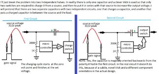
My collaborators would never forgive me for posting the actual diagram, but I THINK I can hide the patentable elements from view and just show enough to make the problem clear. Unfortunately the novel aspect of the circuit is a clever trick so that only two switches are required, and without seeing the trick, it is impossible to understand how it could work. (It does work fine in the simulator software.) I think what I can do is break the problem into two parts and post a diagram as though there were two independent capacitors, but it will take bit of thought to do that in a way that still captures what the circuit needs to do. I'll work on it and come back later with something.

-gt-
--- Updated ---

As I said in my previous reply, I can't divulge the novel trick that is used so that the capacitor doesn't have to "flip" polarity, so instead I've crafted my diagram as though we were talking about two independent circuits. A microcontroller with an ADC monitors the supply voltage and when it begins to rise from zero, the capacitor in the first diagram begins charging until some specific voltage is reached, then the charging cycle stops. In the second diagram we have a pre-charged capacitor that is inserted in series with the source voltage and raises it initially by the amount of the capacitor voltage. As the source voltage rises and then falls to zero, the capacitor will also discharge to zero. I can't say why we would want this behavior but that's what we want to do. I think we can treat this as two separate independent problems. The diagram follows:
 

Attachments

  • SimplifiedCircuit.jpg
    SimplifiedCircuit.jpg
    369 KB · Views: 65
Last edited:
Hi,

with a capacitor in series you can´t avoid those "current peaks" by referring the timing to the AC input voltage.
The correct timing needs to be done via the voltage across the switch.

And still then you need to take care that the capacitor voltage does not drift away. If there is a mismatch in positive and negative halfwave average current, then the voltage of the capacitor may drift (integrate) in one direction. Making the capacitor voltage bigger and bigger ... and the switching currents may become bigger and bigger.

Klaus
 
Congratulations for posting the first images after 9 longwinded text messages.

In terms of SSR specs this is an AC/DC type (AC = bipolar output voltage, DC = on/off capability). They are typically implemented by anti-serial MOSFET or IGBT pairs. If I'm misinterpreting the description and the voltage across the switch is only unipolar, a DC SSR type would suffice.

I don't see off-the-shelve 500V/50A (or more) AC/DC SSR on the market, at first sight the effort exceeds your initial $50 mark by a large factor.

Let's assume you want to assemble the circuit from discrete components, then switch selection and driver design are the major tasks, additionally mechanical integration/heatsinking and overvoltage/overcurrent protection as far as necessary.

You already mentioned switching speed requirements, isolation voltage is another important parameter. In case of doubt, separate isolated DC/DC and gate driver are the way to go. There are however gate driver IC with built-in power supply isolation.
 
Respectfully, your "clever " circuit has been done a million times before, it is easy to construct a circuit that allows charging and then puts the C in series with the source - this is commonly done in industry at a variety of power levels,

as suspected - you have overlooked the currents that may flow in the cap at charge up ( due to source inductance and other reasons ) - and potentially high peaks of current in the load - also if this equipment is operated continuously it needs to meet the requirement for no DC in the mains - this is for earth stake corrosion reasons and others, so there had better be a bridge rectifier in the source side circuit ....
 
Last edited:

LaTeX Commands Quick-Menu:

Part and Inventory Search

Welcome to EDABoard.com

Sponsor

Back
Top