Continue to Site

Welcome to EDAboard.com

Welcome to our site! EDAboard.com is an international Electronics Discussion Forum focused on EDA software, circuits, schematics, books, theory, papers, asic, pld, 8051, DSP, Network, RF, Analog Design, PCB, Service Manuals... and a whole lot more! To participate you need to register. Registration is free. Click here to register now.

Need Advice for High Current, High Voltage, High Speed, Switching

townsend

Member level 1
Joined
May 19, 2023
Messages
32
Helped
0
Reputation
0
Reaction score
1
Trophy points
6
Activity points
417
Hello everyone!

I'm new here - just freshly registered. I have a PhD in Neuroscience, with other degrees prior in Mathematics and Computer Science, and prior to that I earned diplomas from college in the areas of Electronics and Electrical. I don't profess to be a formally recognized "Engineer" and do not have the PEng designation, but my formal study of the area at the college level was carried through as I worked on my Undergrad, Master's and Phd, and I do have two patents registered to my name in the area of EEG acquisition electronics.

Put simply, I might not be familiar with all the jargon that PEng's use, but I have a good grasp of the principles and am able to design my own stuff and debug/troubleshoot other peoples' designs. So, please excuse me in advance if I don't seem to follow what you are saying - its just a matter of us speaking different working languages.

So, here's my question:
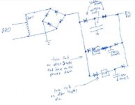
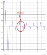
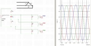
I am in the middle of trying to implement an idea, but I'll spare you all the details and only include what is necessary to help describe my problem. I have a system operating at about 680V and about 40A, and I need to be able to switch a component in and out about 120 times per second. I am under the gun to get a prototype completed fast, and so instead of working on my own switching mechanism, I chose to use a solid state relay (SSR). I chose one with random on/off (i.e. it doesn't wait for a zero crossing, but switches when you tell it to). I also need optical isolation to simplify the connection to the microcontroller that will be handling the timing.

To guarantee perfect operation, I really need sub-millisecond timing accuracy. I also don't want to break the bank with the project, so I wanted to keep the cost of the switch under $50. Unfortunately, the only solution that I found indicated in the datasheet that the device would switch on (and off) within 1 millisecond of being told to do so.

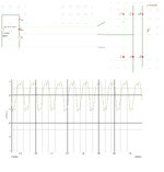
I was disappointed but checked my calculations and found that although not ideal, this would produce "acceptable" results. Without providing all the details, the potential for the delay will result in the output voltage of my project being generated to be a little higher or lower than desired, but still within acceptable limits.

1/ Can anyone point me to a SSR that can respond within 100usec, is within budget, and meets the voltage and current requirements?
2/ Can anyone point me to a resource to help me design my own switching system so I don't need to use a ready-made SSR?

Regarding question 2 above, I specialize in low current low voltage analog and digital applications, so "power electronics" is not a familiar area for me. That's why I'm here seeking some advice. Thanks in advance!
-gt-
 
Voltage semi-doubler using capacitors. Just to show what may be possible without a transformer or autoformer. I present it since I don't expect it to be my million dollar idea. Anyway it's untested in hardware and needs time and effort before it can be made into a solution.

Capacitors charge in series during one half of the cycle...

Then discharge in parallel during the second half while adding voltage of the mains AC sine wave.

Transistors turn on at the proper time automatically, steer current through the load.

View attachment 182904

There is also the classic bridge voltage doubler, a simpler circuit using 2 caps and 2 diodes. It can be used in the same fashion by installing transistors which produce AC at the load. It puts greater stress on components, and draws greater current from house wiring.
Very interesting circuit! Thanks for that. Can you clarify a few things for me on it? The 230 VAC input only has one terminal shown - is the other terminal the circuit ground? Out1 and Out2 I assume are just circuit reference points and not the actual output - is that correct? I assume the actual output is where the 50 ohm load resistor exists? Thanks.
-gt-
Yes your understanding is correct.
 
Hi everyone,
The jury is still out on the transformer regarding the price. I'm hopeful though. So I'm now looking ahead at the resulting issue, which remains in line with my original post in the sense that it still involves solid-state optically isolated low-delay switching, and it also continues to involve the capacitor issue that some of you brought up. So ... new twist, old story.

Here's where things stand: If I use a 160VAC transformer (whether auto, or isolation with secondary in series with the line), I now have the right voltage (380) but I do not have three phases. As I said, I'm going to use single phase, however the remaining problem (other than the higher current, which I can deal with) is that the existing filter capacitors are not going to cut it. They were chosen to deal with the output of a three-phase bridge, and I will either use the diodes inside the unit or replace with higher current ones if needed. The output will be that of a four diode, single-phase bridge rectifier and will need more smoothing.

So the first temptation is to just add extra capacitors in parallel with the existing ones, but of course I've been enlightened by Klaus et. all about this. Whatever is already there is happy with the inrush of current when the device is initially turned on. If that is the case, then can I just switch a second bank of caps in after the first bank is charged after an appropriate pause, then do this again with a third bank? The switches would remain on until power down. I expect I need to triple the total capacitance, to get appropriate filtering, but think I would need to introduce this over an appropriate period of time. I'm thinking one or two AC cycles for each stage?

I can be more specific once I get deeper into the PSU, but does anyone have any initial thoughts about how I might handle this? Is there a better way to handle this than my suggestion? For example, can I do something with inductors? Any suggestions would be appreciated. Thanks.
-gt-
--- Updated ---

*sigh* I just realized that the first bank charges from zero, but the others get slammed into a charged bank(s). So this won't work ... what do I do???
--- Updated ---

... would I have to use a separate set of diodes to isolate the next bank of caps from the previously charged ones, and charge the new bank from zero after the previous bank was charged? This is getting ugly ...
--- Updated ---

... maybe something like this sketch?
--- Updated ---

Here's a jpg image:
 

Attachments

  • sketch.pdf
    106.4 KB · Views: 56
  • sketch.jpg
    sketch.jpg
    101.6 KB · Views: 56
Last edited:
Not to jerk this thread back toward practical solutions or anything,
but since the end game here -is- 3 phase industrial grade power
from 2-phase, are you (OP) convinced that there's not one crusty old
yet still serviceable rotary converter sitting in a surplus warehouse
anywhere within affordable freight distance?

Whole lot less "learning opportunity".
Thanks for the response. I appreciate your continued assitance!

The only problem with your suggestion is that I'm not sure how noisy that will be, and my motivation for getting these new units is they are water cooled and I am trying to use them to replace units that are air cooled and currently make my shop sound like an airplane taking off. I suspect the rotary motors won't be as noisy, but it still defeats the purpose of doing this since I'm trying for a fan-less shop. The water-cooled units all use three-phase power. So having a dozen motors running might still be pretty noisy. The other issue is they will run 24/7, and I was concerned about the mechanical wear they would undergo. So, I did consider it, but I don't think it will achieve my goals.

On the other hand, I'm not opposed to generating three-phase power if it is more cost effective. I do have access to a source of 1-to-3-phase converters for motors, and I even purchased one (cheap and under-sized for the project) just to get familiar with the devices. It is only 2KW. It only arrived last week and I haven't played around with it yet, however I had planned on using it in conjunction with a transformer, or reactor, or a sine filter and have been pricing out these options. The problem is the unit puts out PWM on the three phases. Supposedly it converts 220v to 380v, however when I queried the salesman about the details, he insisted that the output voltage was 380 MAX and not the 380Xroot(2) that it should be. It was cheap (undersized for this project) so I bought it anyway to experiment with, and the first thing I will do over the next few days is see if he was right about that. I asked how it could produce 380 3-phase if the PWM output doesn't reach 537V and he said, "that's why it saves power when running motors". He could be right, but I'm skeptical.

Now that I weigh everything out, I'm wondering (depending on the true peak voltage of the PWM output) if it might not be okay to drive the three phase bridge in the target PSU with. It can be programmed to ramp the voltage up. I am concerned about putting PWM onto the bridge because of the filter caps in the PSU, but if the voltage was ramped up over one second, maybe the caps would charge to peak slowly enough to be okay and not draw too much startup current?

The 1-to-3 PWM device was never intended for this purpose, but as I think about it, maybe connecting PWM output, (ramped up from zero) to a 3-phase bridge, might not have any negative consequences and might work fine. I know it is extremely unorthodox to feed it with PWM, but at first blush, I don't immediately see any theoretical issues that would stand in the way of it working fine. Once the filter caps reach peak voltage, the PWM won't make a lot of difference, especially since at all times at least one of the phase pairs will be outputting a flat peak voltage for a long period of time while the other phases are "diddling" around.

Your thoughts?

-gt-
p.s. the water-cooled units are not only silent, but as computers, the superior cooling results in them being three or four times as powerful, so its not just "quiet" that I'm after here. Not only are the PSUs water cooled, but the computers paired with them are also water cooled.
 
We kinda all were wondering when the issue of cap size was going to hit your consciousness,

really to soft start the caps you need SCR's ( say two upper or two lower ) in the diode bridge - these can be gradually gated from 180 deg to 0 degrees over 30 sec say to bring up the cap bank - BUT

the bigger problem you are un-aware of is the rms current in the input bridge that will be feeding these caps

the power factor of a cap input filter ( after a diode bridge ) is about 0.5 - 0.6 for very large cap banks

So for 5300 watts DC out, the VA drawn is 9636 ( PF = 0.55 ) which for 220Vac = 44A rms

[ The reason here is that current only flows in a narrow tall spike when Vmains exceeds the V on the caps - so the peak currents will be > 100A ]

So the diodes will run pretty warm unless well heatsunk ( a standard 50A bridge will not hack the pace here )

the wires, the caps, all will be seeing big currents .....
--- Updated ---

Also if your gear is designed for 3 phase in @ 380VDC, internally after the 6 diode bridge the voltage is ~ 500VDC ave with 15% ripple, i.e. it is relatively smooth for the following stages

If you feed it with single phase - the internal storage caps, - which are designed for a 3 phase feed and are therefore quite small - will not be able to hold up the 500VDC over the gaps in the single phase feed ( there are effectively no gaps for 3 ph in ).

This is why the PFC booster solution looks the best, it has unity power factor in ( 5330W = 220Vac, 25A ac )

and a solid output voltage ( due to large caps )

which can then be fed to your following equipment ....
 
Last edited:
We kinda all were wondering when the issue of cap size was going to hit your consciousness,

really to soft start the caps you need SCR's ( say two upper or two lower ) in the diode bridge - these can be gradually gated from 180 deg to 0 degrees over 30 sec say to bring up the cap bank - BUT

the bigger problem you are un-aware of is the rms current in the input bridge that will be feeding these caps

the power factor of a cap input filter ( after a diode bridge ) is about 0.5 - 0.6 for very large cap banks

So for 5300 watts DC out, the VA drawn is 9636 ( PF = 0.55 ) which for 220Vac = 44A rms

[ The reason here is that current only flows in a narrow tall spike when Vmains exceeds the V on the caps - so the peak currents will be > 100A ]

So the diodes will run pretty warm unless well heatsunk ( a standard 50A bridge will not hack the pace here )

the wires, the caps, all will be seeing big currents .....
--- Updated ---

Also if your gear is designed for 3 phase in @ 380VDC, internally after the 6 diode bridge the voltage is ~ 500VDC ave with 15% ripple, i.e. it is relatively smooth for the following stages

If you feed it with single phase - the internal storage caps, - which are designed for a 3 phase feed and are therefore quite small - will not be able to hold up the 500VDC over the gaps in the single phase feed ( there are effectively no gaps for 3 ph in ).

This is why the PFC booster solution looks the best, it has unity power factor in ( 5330W = 220Vac, 25A ac )

and a solid output voltage ( due to large caps )

which can then be fed to your following equipment ....
--- Updated ---

Thanks "Easy-peasy". Well, I did recognize the need for additional filtering as I mentioned earlier, but you've brought forward a lot of additional issues that are important. Given all that, I'm wondering if the 220v-single-phase to 380V-three-phase PWM modulated solution might work. There are a few issues you brought forward that I think are mitigated by it. First, we don't have these single-phase bridge humps that go all the way to zero, but we ALMOST have DC coming out of the bridge. I think it is actually less "humpy" than a true 3-phase sinusoidal signal would be, since for a fairly substantial number of degrees, the PWM output of at least one phase is full voltage, and it barely has time to drop before a different phase pair "sticks" on full. I won't know the details until I test it properly, but I did put a 'scope on one of the outputs and noted that the voltage parked high for quite a while. before resuming the thinner pulses in the PWM modulation sequence. As I said, extremely unorthodox, but maybe workable? I don't think I'll have to touch the PSU's filter at all ... if anything, the caps could probably be reduced in size given the waveform that will come out of the bridge.
-gt-
p.s. anything involving a transformer or coil seems to be very costly so far, but if PWM can work directly, maybe that's all I need. The 2kw unit was only something like $160. Of course the bigger ones are more, but proportionally so.
 
Last edited:
How do you get from 220V single phase to 500VDC for the 3 phase pwm ckt to work on ?
The unit has a votlage doubler which gives 622 VDC. They refer to that as their "internal DC BUSS voltage". Then they convert is back to PWM on three output wires.
--- Updated ---

The unit has a votlage doubler which gives 622 VDC. They refer to that as their "internal DC BUSS voltage". Then they convert is back to PWM on three output wires.
More information for you on this: I think each output is (with respect to the internal "circuit ground") either 0 or +537V at all points in time. Depending on which wires have zero and which have the positive voltage, current flows in one phase and out the other, then reverses. The average DC voltage across any pair of phase wires is zero. You don't need a negative voltage to achieve this (maybe a little counter intuitive till you think about it).

This is based on a combination of what the sales agent told me and what I read about these units. I can confirm tomorrow once I set it up and play around with it. I can already confirm that there is a display that you can set to output different parameters, including this internal DC BUSS the agent mentioned, and the display shows 618V for that ... maybe 622 minus some diode/switch drops?

Anyway, tomorrow I'll know a lot more about the unit. Since it is not isolated from ground, and I want to correctly measure differences of potential, I've ordered parts to build an attenuation pad and an isolation transformer for my laptop's power supply (no ground) so that I can connect a digital data logger direct across any two phases and digitize the result. I did something like this in the physics class I teach when we studied the current drawn by a cold incandescent 60W light bulb and showed how it draws an enormous current for a very short time while the filament heats up. Anyway,, I had to isolate my laptop and the digitizer from ground and house power to safely do this. So this is similar. Tomorrow I can post the wave forms for you to show you what they look like, but you can consult lots of sources on the internet to see them. If you don't hear back, then I guess you can assume that I've electrocuted myself.
-gt-
 
Last edited:
OK - suspected voltage doubler, this will draw 44 A rms @ 220Vac in for 5300 watts, per the above

I hope it's rated .....
Yikes!!! I'll have to throw that into the circuit simulator right away, first to confirm what you are saying, and then to try and understand why that would be the case. If that's correct, then this is not a solution at all.
-gt-
--- Updated ---

Yikes!!! I'll have to throw that into the circuit simulator right away, first to confirm what you are saying, and then to try and understand why that would be the case. If that's correct, then this is not a solution at all.
-gt-

I got the computer to calculate the RMS from the waveform ... 44 amps, just like you said. I see also there's a ridiculously high current for the first cycle when the caps are dead. Shesshshshs!!!!!
 

Attachments

  • 44amps.jpg
    44amps.jpg
    88.7 KB · Views: 64
Last edited:
The impedance of the mains supply will limit the currents a little bit - and you will flat top the 220V sine

but yes - the currents, rms, will be high ....
 
Theoretical example of what's possible. Inductor/capacitor amplifies AC and introduces phase shift.

Choose LC values to resonate at supply frequency. By adjusting LC ratio you can:

a) obtain desired voltage to load
b) shift waveforms by 1/3 cycle (imitating 3-phase power)

LC series 230 VAC increase and delayed 120 n 240 degrees.png
 
Theoretical example of what's possible. Inductor/capacitor amplifies AC and introduces phase shift.

Choose LC values to resonate at supply frequency. By adjusting LC ratio you can:

a) obtain desired voltage to load
b) shift waveforms by 1/3 cycle (imitating 3-phase power)

View attachment 182940
--- Updated ---

Thanks for that - I'll play with it in the simulator to understand it better.
-gt-
 
I tried this as a delta load of 47 ohms in each phase pair, and by playing with the components I approximately balanced the three phases. I was able to get the voltages up to the required 537 peak, but not all three simultaneously. I also tried the 3P rectifier on it, which messed up the balanced phases.

I suspect that tweaking the components in the version with the rectifier would balance up the phases and eliminate that low drop in the second diagram.

I guess the main problem is that the behavior of this circuit is highly dependent on the load, making it unsuitable for the project. :(
 

Attachments

  • simulation.jpg
    simulation.jpg
    300.1 KB · Views: 49
  • sim2.jpg
    sim2.jpg
    342.8 KB · Views: 53
Hi,

the problem with the "phase shifted" voltages is, that you may "adjust" it for a fixed known linear load.

But as soon as the load is a non linear diode circuit, it may mess up. In worst case - if you disconnect the load you may get very high resonance voltage. The circuit may kill itself.

****

Indeed over the 55 posts ... I lost the true goal of the circuit.
DC, AC, single phase, 2 phase, 3 phase, load connection (star, delta), rectified, with capacitor...

Klaus
Yes, we've been all over the place, but in the end the true goal from my perspective is to find an economical way to operate a 380V, 5300W, three-phase PSU from single-phase 220VAC 60 Hz with an ECONOMICAL solution (whether it includes modifications to the PSU or not). Since I'm looking at 12 or 13 pieces of equipment, there is great motivation for me to come up with a cost effective AND EFFICIENT solution, and it is worth me sinking a lot of effort into exploring options and finding the best solution. It might not be the best use of other forum members's time, but by the number of responses, it seems people are happy to help, and I really do appreciate that, and I don't take it for granted. Thanks to everyone for all the help!

So far, I think the most viable solution might be the autotransformer with an approach to switch the extra capacitance required incrementally in over a certain length of "boot up" time. The required transformer at this point is a custom job and prices out over $700 (CAD). I'm still looking for a ready-built alternative at a lower cost. If this is the best choice, then the final topic remains consistent with my original post since I WILL still need to do some solid state switching.

It sounds like the SCR idea someone proposed to charge the caps up might be the easiest approach, especially since I require those isolation diodes in my related sketch anyway - they could just as easily be SCRs instead.
-gt-
 
Update:

I tested the phase converter's output and it turns out that it outputs its full DC BUS voltage to the the three phase outputs, PWM with 0V as the low voltage and +622VDC. So it doesn't output the 380V the agent claimed nor the 537 that I hoped it might. He wouldn't say if the input stage contained a voltage doubler, but instead said that to calculate the input current, we multiply the output phase currents (8A current in each of the three phase wires) by 2.5 which is of course nonsense, since that results in only 4429 Watts input power and 5300 Watts (8A per phase at 380V = 8Xsqrt(3)X380) output power. So I'll have to hook up a small resistive load and check myself to see what it really does.

However, because the output voltage is so high (622) the "flat spot" I predicted near the peak doesn't happen. Obviously the product works fine on a motor where we have inductance, but it is clear I can't put this device on a rectifier feeding capacitors. So I think I can rule this solution our completely now.

In the meantime, my thousand dollar transformer can be custom made in China, so I'm going to explore that (using a 160V transformer in series with the 220 line voltage). The price is significantly lower that quoted in Canada, but shipping is costly. However, they are willing to send a free sample, and if I can make it work, the other dozen can be shipped by sea at a relatively low cost per unit.

So it looks like the remaining challenge is how to add filter capacitance in a way that doesn't cause trouble.
-gt-
 
220Vac + 160 Vac in an auto Tx = 380Vac ( 540V pk + 15% max worst case on the mains = 620Vpk )

[ so hopefully inside the equipment there are stacked 350 / 400V caps to give an 700/800V withstand ]

At 5300 watts required, with a bridge and large caps the current out of the auto Tx will be 26A rms

at the 220V side this will be 45A ( I have allowed a little for losses ) still.

Feeding DC into the following equipment seems like a good idea ( they are psu's correct ? )

The only way to improve upon this scenario would be a controlled bridge with a large output inductor - but this would prove bulky, and heavy and more complex, and the VDC out would be the average of the mains, so 380Vac becomes 342VDC ave, the currents in the system would then be nearly square ( for a large output L ) so the rms currents would be minimium.
Thanks a lot for taking the time to think that through and make those suggestions. I purchased just the PSU unit of the equipment ($7000 for the entire machine, but just under $400 for the PSU by itself). I'd rather spend $400 and fail than $7000 and fail! :)

It arrived yesterday but is 1/4 mile away in the USA. I'm in Canada, but I'm going on a Caribean cruise next week, and will drive into the states and to an airport there. I'll bring it back with me upon my return ... duty free and tax free, because of the time spent in the states. :)

So I won't have it until I'm back from my (fairly short) vacation. When I get it home I can cut it open and see what is there and report back to you. As far as charging the caps up, I've carefully considered all that the members have enlightened me on concerning caps, and put together a REALLY old-school solution that will cost about $25 in total (Excluding the costs of the additional filter caps and the transformer). I think you'll laugh pretty hard when you see it. So far you've been spot on, always thinking ahead, so I suspect that my description is enough to get the wheels in your mind turning, and you'll probably be able to deduce where I'm going with this based on my very sketchy description above. I can probably breadboard and pre-test it without the transformer, since charging that much capacitance remains a challenge even at 220V. So once I get it constructed, I'll fire it up and monitor the currents and if it works, I'll send a schematic and some pictures and wave forms.

I suppose by then you'll have figured it out and posted what I have in my head. :)

Thanks again for the help!
-gt-
 

LaTeX Commands Quick-Menu:

Part and Inventory Search

Welcome to EDABoard.com

Sponsor

Back
Top