Jose Enrique Sanchez V.
Newbie level 5
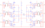
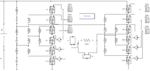
I'm an engineering student from Spain, I've been doing my final assessment about different power electronics, inverters, controlled rectifiers, DC/DC and AC/AC simulated with Matlab Simulink. As the last subject in my project I have decided to do an circuit of a multilevel inverter, which tries to change +12Vdc to a sine wave from +12v t0 -12V, controlled by my FPGA artyA7 and I am having problems to activate the 12 mosfets...
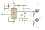
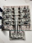
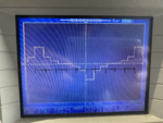
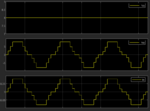
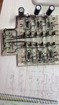
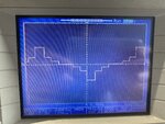
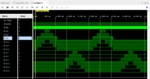
Finally I had had decided to try with an bridge inverter with only 4 mosfets and two driver IR2110 and I achieved that my design worked fine. Now I am working again with the multilevel inverter, with 12 mosfets and 6 IR2110. It has the right shape with 7 levels as you can see in the pic, but the frequency is 3 times the wanted. I design the vhdl code for my fpga to 400hz and as you can see in the simulation it's ok, and when I use an oscilloscope to see every output of the development fpga board it has 400hz... Maybe the oscilloscope the the measure wrong, from wrong time or in the wrong way, because apparently the design is well done???
for your advises

")