Continue to Site

Welcome to EDAboard.com

Welcome to our site! EDAboard.com is an international Electronics Discussion Forum focused on EDA software, circuits, schematics, books, theory, papers, asic, pld, 8051, DSP, Network, RF, Analog Design, PCB, Service Manuals... and a whole lot more! To participate you need to register. Registration is free. Click here to register now.

multi cycle path example code implementation

Status
Not open for further replies.

kommu4946

Member level 4
Joined
Feb 21, 2014
Messages
71
Helped
13
Reputation
26
Reaction score
11
Trophy points
1,288
Location
India
Activity points
1,846
Hi,
i have seen example code for multi cycle path in below link.
https://www.edaboard.com/threads/333626/
i am trying to understand multi cycle path implementation using above code in vivado.
Code:
module mc_test(
 input    wire     board_clk,
 input    wire      rst,
 output   reg [3:0] ff_1,
 output   reg       ff_2
 );


 clk_wiz_0 pll
    (
     .clk_in1(board_clk),      
     .clk_out1(clk));  

  reg [1:0] cntr;
  reg [8:1] lfsr;

 
  always @ (posedge clk) begin
    if (rst) begin
      cntr <= 0;
    end else begin
      cntr <= cntr +1;
    end
 
    if (rst) begin
      lfsr <= 1;
    end else begin
      lfsr <= {lfsr[1], lfsr[8], lfsr[7]^lfsr[1], lfsr[6]^lfsr[1], lfsr[5]^lfsr[1], lfsr[4:2]};
    end

  end
 
  // multicycle registers
  always @ (posedge clk) begin
    if (cntr == 2'd3) begin
      ff_1 <= lfsr[4:1];
      ff_2 <= ff_1;
    end
  end
 
endmodule

i used clock as 50 mhz. i got the following timing report

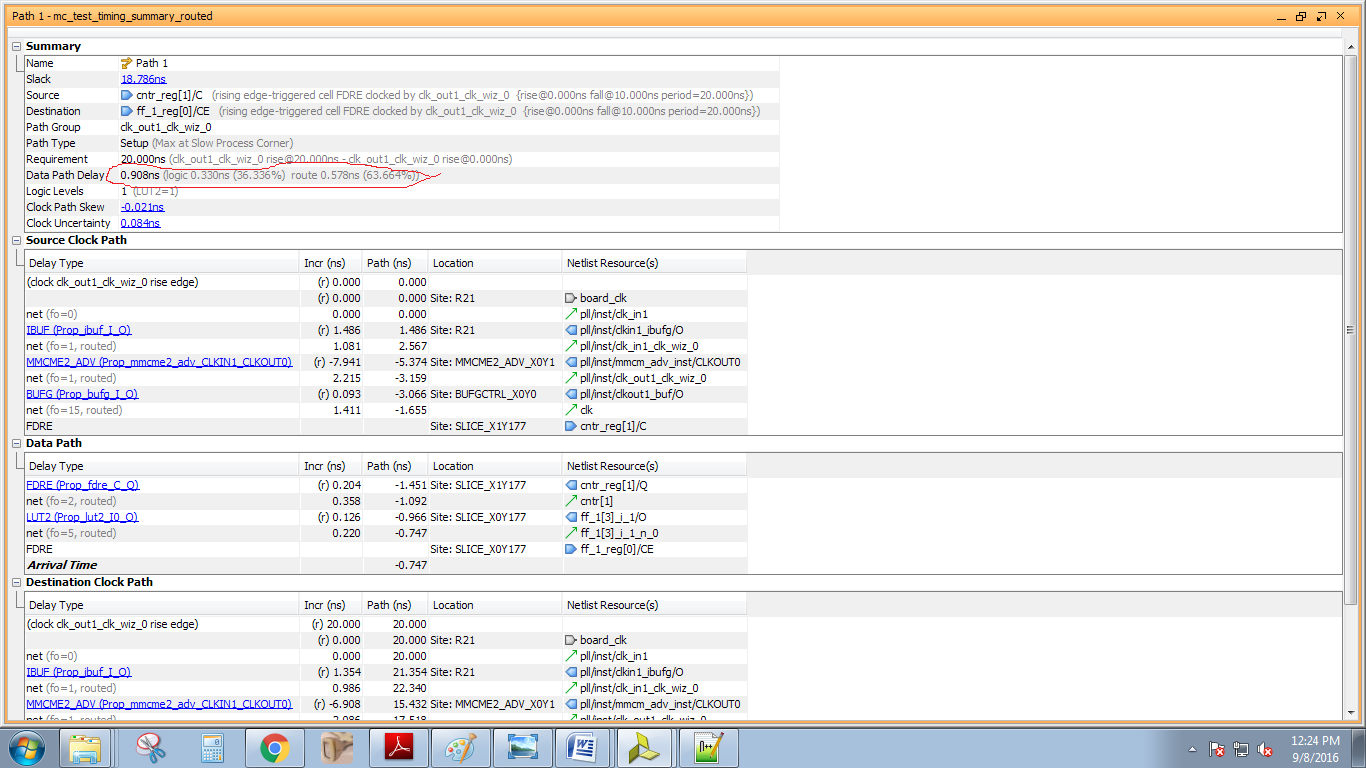
here i got the data path delay as 0.908ns which is still less than one clock cycle of 50 mhz clock.
should i declare multicycle path constraint even though it is not exceeding more than one clock cycle ? i studied about multicycle path constraints which states that if the combinational delay is more than one cycle delay it is should be declared as multi cycle path


Regards
 

the example above doesn't work without a multicycle constraint.
 

the example above doesn't work without a multicycle constraint.

I don't see why it wouldn't work without the multicycle constraint, this might have been the case in a much older technology node than today. At 50 MHz this will make timing on any part in that Vivado can implement without multicycle constraints (which is what the OP observed).

Try implementing a 64-bit * 64-bit (C = A*B) non-pipelined multiplier with a 400 MHz clock on the input and output registers and I'm pretty certain that won't make timing and would require a multicycle path from the A and B inputs to the C output register.

allow me to explain
- the code has one clock domain, so all the logic, everything, is on the same clock domain
- cntr is updated every single cycle, as it is a simple counter
- the if statement (if (cntr == 2'd3)) will be translated to combinational logic, meaning it updates at every clock cycle
- that means you effectively have a timing path that starts at cntr and ends at both ff1 and ff2
- because cntr updates every cycle, it cannot be a multicycle path. vivado cannot decide that for you. this is a very simple scenario where we clearly see a counter and know what the intent is, but vivado can't see it the way we see it.

the example is a super simple lfsr code, essentially just a bunch of xor gates. off course it will meet a 50mhz timing. it doesn't mean it is multicycle though.

That means every multi cycle registers is not needed to constrain as a multicycle path? or we need to put a multi cycle if and only if there is a combinational delay more than one clock cycle? which one is correct?

**broken link removed**
In above link page no 289 last paragraph states that "From an optimization perspective, another guideline is to not use a false
path when a multicycle path is the real intent. If a signal is sampled at a
known or predictable time, no matter how far out, a multicycle path specification
should be used so that the path has some constraint and gets optimized
to meet the multicycle constraint. If a false path is used on a path that is sampled many clock cycles later, optimization of the remaining logic
may invariably slow this path even beyond what may be necessary"
it is some what confusing with your explanation


Regards
 
Last edited:

That means every multi cycle registers is not needed to constrain as a multicycle path? or we need to put a multi cycle if and only if there is a combinational delay more than one clock cycle? which one is correct?

**broken link removed**
In above link page no 289 last paragraph states that "From an optimization perspective, another guideline is to not use a false
path when a multicycle path is the real intent. If a signal is sampled at a
known or predictable time, no matter how far out, a multicycle path specification
should be used so that the path has some constraint and gets optimized
to meet the multicycle constraint. If a false path is used on a path that is sampled many clock cycles later, optimization of the remaining logic
may invariably slow this path even beyond what may be necessary"
it is some what confusing with your explanation


Regards

I think you got confused. The pdf you linked is pretty clear. This is how you properly build a multicycle path:
a) do the RTL code with the multicycle path in mind. if you are sampling from a multicycle path, you must only do when the data is actually valid.
b) having a multicycle "notion" coded into RTL is not sufficient -- that is why the example above doesn't work on its own
c) specify a multicycle constraint with a start point and an end point
d) do not specify a false path on it.

a) what i understood from that paragraph is (assume same clock domain)if we sample the signal at known time we should declare it as a multi cycle path.suppose if i sample the signal for every four clock cycles we should declare setup and hold multiplier in multicycle path as 4 and 3 for start and end point. suppose if i sample signal for every 64 clock cycles then the setup and hold multiplier should be 64 and 63 respectively.in this way we should declare corrsponding numbers based on sampling instants. is it right or not?
b)suppose i forgot to declare them as multi cycle path then also it working ( i tested in one of my design .assume 50 mhz) where the tool will do STA for every clock cycle that is set up check is one clock cycle after the launch and hold check is done on the data launch clock it self and also it is not reporting any slack.now then i declared the path as multi cycle path where STA will do set up check after four clock cycles of launch edge and hold check is moved back from default hold check to three clock cycles(I.e. launch clock edge)then also not getting any slack violations.

So here my question is can i ignore multi cycle constraint if the combinational delay is not more than one clock cycle? if that is the case is both are same one is no multi cycle path and other is multi cycle path?
c) please see the below case attached in figure where the data is coming at 27 mhz and data is valid for three clock cycles. suppose if i want to transfer data from 27 mhz to 50 mhz which are async .i am sampling the 27 mhz signal in the 50 mhz clock domain using two flop sync and edge detection and i declared the clock domain crossing as false path even though the data is changing after few clock cycles. In this case should i declare the data pins as a multi cycle path ( i specified false path constraint is pin to pin for valid signal .if its is clock domain to clock domain it has high priority over multi cycle path)https://obrazki.elektroda.pl/1401701300_1473444346.jpg

Regards
 

a) that is right.
b) if it fits, it fits. if it passes a setup check, you probably wouldn't want to make a multicycle path out of it.
c) this is different. this is not a typical multicycle path, this a domain crossing problem. you shouldn't use a multicycle path for this.
 

actually i observed synthesis schematic which shows that cntr is actually mapping to clock enable pin of flipflops(0 to 3) and ff_2 (FDRE).Should i declare multi cycle constraints on CE pin or data pin of flip flops? which is correct here i am attaching constraints files.
set_property PACKAGE_PIN R21 [get_ports board_clk]
set_property IOSTANDARD LVCMOS33 [get_ports board_clk]
set_property PACKAGE_PIN D13 [get_ports rst]
set_property IOSTANDARD LVCMOS33 [get_ports rst]
set_property PACKAGE_PIN F18 [get_ports {ff_1[0]}]
set_property IOSTANDARD LVCMOS33 [get_ports {ff_1[0]}]
set_property PACKAGE_PIN N26 [get_ports {ff_1[1]}]
set_property IOSTANDARD LVCMOS33 [get_ports {ff_1[1]}]
set_property PACKAGE_PIN F17 [get_ports {ff_1[2]}]
set_property IOSTANDARD LVCMOS33 [get_ports {ff_1[2]}]
##D5
set_property PACKAGE_PIN M26 [get_ports {ff_1[3]}]
set_property IOSTANDARD LVCMOS33 [get_ports {ff_1[3]}]
##D6
set_property PACKAGE_PIN E17 [get_ports ff_2]
set_property IOSTANDARD LVCMOS33 [get_ports ff_2]

set_multicycle_path -setup -from [get_pins {cntr_reg[0]/C}] -to [get_pins {ff_1_reg[0]/CE}] 4
set_multicycle_path -hold -from [get_pins {cntr_reg[0]/C}] -to [get_pins {ff_1_reg[0]/CE}] 3
set_multicycle_path -setup -from [get_pins {cntr_reg[0]/C}] -to [get_pins {ff_1_reg[1]/CE}] 4
set_multicycle_path -hold -from [get_pins {cntr_reg[0]/C}] -to [get_pins {ff_1_reg[1]/CE}] 3
set_multicycle_path -setup -from [get_pins {cntr_reg[0]/C}] -to [get_pins {ff_1_reg[2]/CE}] 4
set_multicycle_path -hold -from [get_pins {cntr_reg[0]/C}] -to [get_pins {ff_1_reg[2]/CE}] 3
set_multicycle_path -setup -from [get_pins {cntr_reg[0]/C}] -to [get_pins {ff_1_reg[3]/CE}] 4
set_multicycle_path -hold -from [get_pins {cntr_reg[0]/C}] -to [get_pins {ff_1_reg[3]/CE}] 3
set_multicycle_path -setup -from [get_pins {cntr_reg[0]/C}] -to [get_pins {ff_2_reg/CE}] 4
set_multicycle_path -hold -from [get_pins {cntr_reg[0]/C}] -to [get_pins {ff_2_reg/CE}] 3

set_multicycle_path -setup -from [get_pins {cntr_reg[1]/C}] -to [get_pins {ff_1_reg[0]/CE}] 4
set_multicycle_path -hold -from [get_pins {cntr_reg[1]/C}] -to [get_pins {ff_1_reg[0]/CE}] 3
set_multicycle_path -setup -from [get_pins {cntr_reg[1]/C}] -to [get_pins {ff_1_reg[1]/CE}] 4
set_multicycle_path -hold -from [get_pins {cntr_reg[1]/C}] -to [get_pins {ff_1_reg[1]/CE}] 3
set_multicycle_path -setup -from [get_pins {cntr_reg[1]/C}] -to [get_pins {ff_1_reg[2]/CE}] 4
set_multicycle_path -hold -from [get_pins {cntr_reg[1]/C}] -to [get_pins {ff_1_reg[2]/CE}] 3
set_multicycle_path -setup -from [get_pins {cntr_reg[1]/C}] -to [get_pins {ff_1_reg[3]/CE}] 4
set_multicycle_path -hold -from [get_pins {cntr_reg[1]/C}] -to [get_pins {ff_1_reg[3]/CE}] 3
set_multicycle_path -setup -from [get_pins {cntr_reg[1]/C}] -to [get_pins {ff_1_reg[0]/CE}] 4
set_multicycle_path -hold -from [get_pins {cntr_reg[1]/C}] -to [get_pins {ff_1_reg[0]/CE}] 3
set_multicycle_path -setup -from [get_pins {cntr_reg[1]/C}] -to [get_pins {ff_2_reg/CE}] 4
set_multicycle_path -hold -from [get_pins {cntr_reg[1]/C}] -to [get_pins {ff_2_reg/CE}] 3
# MULTI CYCLE CONTSRAINTS FOR DATA PINS
#set_multicycle_path -setup -from [get_pins {lfsr_reg[1]/C}] -to [get_pins {ff_1_reg[0]/D}] 4
#set_multicycle_path -hold -from [get_pins {lfsr_reg[1]/C}] -to [get_pins {ff_1_reg[0]/D}] 3
#set_multicycle_path -setup -from [get_pins {lfsr_reg[2]/C}] -to [get_pins {ff_1_reg[1]/D}] 4
#set_multicycle_path -hold -from [get_pins {lfsr_reg[2]/C}] -to [get_pins {ff_1_reg[1]/D}] 3
#set_multicycle_path -setup -from [get_pins {lfsr_reg[3]/C}] -to [get_pins {ff_1_reg[2]/D}] 4
#set_multicycle_path -hold -from [get_pins {lfsr_reg[3]/C}] -to [get_pins {ff_1_reg[2]/D}] 3
#set_multicycle_path -setup -from [get_pins {lfsr_reg[4]/C}] -to [get_pins {ff_1_reg[3]/D}] 4
#set_multicycle_path -hold -from [get_pins {lfsr_reg[4]/C}] -to [get_pins {ff_1_reg[3]/D}] 3
#set_multicycle_path -setup -from [get_pins {ff_1_reg[0]/C}] -to [get_pins {ff_2_reg/D}] 4
#set_multicycle_path -hold -from [get_pins {ff_1_reg[0]/C}] -to [get_pins {ff_2_reg/D}] 3


end of first constraint file
Which constraints are valid that is counter reg to flip flop registers or
lfsr registers to flip flop registers ?
Here i am attaching the synth schematic also


synth_schematic.png
 

It is not necessary to have all those multicycle paths. The only path that a multicycle constraint would properly apply to is between ff_1_reg [1] to ff_2_reg, which doesn't even have any logic between those registers.

You use multicycle constraint when you can't make timing between pipeline stages that have a guaranteed number of clock cycles between updates e.g. a huge combination multiplier that has clock enabled registers on all the inputs and outputs with the enable only going active every 4th clock.
 
Status
Not open for further replies.

Part and Inventory Search

Welcome to EDABoard.com

Sponsor

Back
Top