Audioguru
Advanced Member level 7
- Joined
- Jan 19, 2008
- Messages
- 9,457
- Helped
- 2,151
- Reputation
- 4,302
- Reaction score
- 2,008
- Trophy points
- 1,393
- Location
- Toronto area of Canada
- Activity points
- 59,720
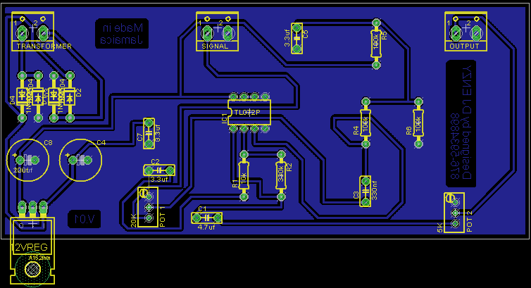
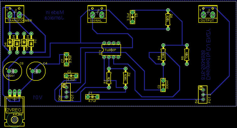
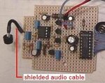
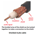
Modern opamps have good high frequency response. If your TL072 is feeding the capacitance of a shielded audio cable that feeds the power amplifier then the capacitance of the cable on the output of the TL072 causes it to oscillate at a high frequency. Add a series 100 ohm resistor from the output coupling capacitor of the TL072 to the cable connection to fix it.
Did you measure the output DC voltage of the opamp? Is it half the supply voltage?
Did you measure the output DC voltage of the opamp? Is it half the supply voltage?