Continue to Site

Welcome to EDAboard.com

Welcome to our site! EDAboard.com is an international Electronics Discussion Forum focused on EDA software, circuits, schematics, books, theory, papers, asic, pld, 8051, DSP, Network, RF, Analog Design, PCB, Service Manuals... and a whole lot more! To participate you need to register. Registration is free. Click here to register now.

[moved] Query about VU meters (led bargraph)

Status
Not open for further replies.
You do not do what I say or show because you do not know what you are doing. Maybe you should do gardening instead and let an electronic guy do your electronics for you.
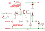
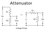
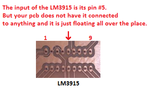
I also made a mistake. This VU meter circuit can show only the output of ONE amplifier. If you connect two amplifiers then the voltage divider provides a voltage that is 2 times too high.
 

Attachments

  • Fixed confusion1.png
    Fixed confusion1.png
    52.4 KB · Views: 77

Apparently I am wasting your time, im not trying to ask more than you can give so for it to reach a point where it seems like your insulting me makes no sense your all mighty and power because this is something you know very well, I havent even gotten a course in it and I like it I just need help to set up a circuit, I didnt come here asking for insults I said many times before that I am new to this seems you find that hard to understand.

1) I came here with my basic circuit with the attenuator already on it and you told me to remove it then you added a peak detector circuit then I made a updated drawing in which you told me I would need the attenuator to cut down the 56v rememer I do not know what an attenuator is but the fact that you told me to remove the 10k resistor from line 5 I assumed thats what you ment so I added the 10k resistor again to line 5 alone with the other 10k to ground (remember that was what you told me to remove when you said remove the attenuator) so the fact that you said to add it to remove the high voltage I did and your reply was that I will blow the circuit up because there is no attenuator so I asked you how can I add ( I was saying to myself I added it but you said I didnt) what you should have said at that time is that the values I have is incorrect but instead all you did was say it would blow up and its not there, so again I added a 10k to ground because you said I should do and remember in my previous drawing I added the 10k at the very input of the circuit and you said I didnt add it so the last drawing I made I added the sae 10k resistor right beside the Ic itself because I thought thats what you ment when you said it wasnt there.

I even made a note in the text telling you that I am not sure where to put the attenuator because when its at the start of the circuit you say its missing and when its closer to the ic you still say its not there ( couldnt you just tell me the value was wrong? Because more than once I sent drawings with the 2 10k resistors I saw in the schematic I was following).

You seem fed up you said you made a mistake and thats ok with me after all helping me isnt your priority so thats understandable because more than once I told you I was using 2 of the chinese amplifiers. So what I am thinking is that I should be able to build 2 of the same vu meter's for the 2 amplifiers, can that work or should I just scrap this and try building a clip/peak light circuit.
 

Apparently I am wasting your time, im not trying to ask more than you can give so for it to reach a point where it seems like your insulting me makes no sense your all mighty and power because this is something you know very well, I havent even gotten a course in it and I like it I just need help to set up a circuit, .

Don't lose heart, it is easy to get lost. Electronics is still something like a black art to me- that all these things work is a big mystery in some way. I was very fortunate that we had a good and patient teacher who will not get angry even when we did make stupid mistakes. Chinese amplifiers are great because they have made it simple and basic and now everybody can have one to play, try out their ideas and innovate. If it goes bad you will not mind to throw it away. The good thing is that they work. That is the minimalist approach- I personally do not see any problem with that.

In other words, if it were an american made amplifier, it would have costed so much that you would not have thought of making any changes to it ever!

It is a question of learning- you need to understand why 5K and why not a 22K. Yes, a voltage divider is an attenuator but a proper one will have a constant input and constant output impedance. That takes more work. Attenuators should be used liberally whenever you feel that the signal is going to overload the next stage.

Once you learn, you will find it simple, almost trivial.
 

Sorry, I am not a teacher. I like to chat about electronics with guys who know electronics. I have helped thousands of people who had problems with an electronic circuit.

Do you know Google? I entered Attenuator (electronics) and found many descriptions and this schematic which is the same as your first one and the same as mine. The circuit you found with the attenuator feeding the LM3915 does not need an attenuator because its amplifier does not have much output power and the input of the LM3915 is fine with up to 35V.

I did not learn about the LM3915 in school. Instead I heard about it, looked at its datasheet (www.datasheetarchive.com), bought one and used it. Its datasheet shows 3 peak detectors.
I went to school before opamps were invented so I learned about them myself. I also learned about many transistor circuits myself.

1) The Chinese amplifier probably does not have enough sensitivity so the opamp is needed to increase its sensitivity. I designed the opamp to be powered from a 12VDC supply. The datasheet and I said that peak levels would appear as a dim blur and that a peak detector circuit would make the LEDs look much better. I planned for the simple transistor peak detector would also use the 12VDC SUPPLY. But the simple peak detector I copied from the datasheet of the LM3915 needs an AC input that goes negative (the datasheet did not say so) and the opamp circuit with its +12V supply will not provide it, so I showed a peak detector using an opamp.

2) The Chinese amplifier has a lot of output power but then its voltage swing is so high that it needs to be attenuated (reduced). An attenuator is so simple that I thought you knew about it but you missed one of its two resistors. I showed the simple calculation.

3) Yes, each amplifier should have its own VU meter. It will show how close or far the level is from clipping, a clip/peak light does not. I never used a clip/peak light, instead I use my hearing.

You are very close to this project's completion.
 

Attachments

  • attenuator.png
    attenuator.png
    7.6 KB · Views: 69

From the context of how you speak and also because it looks like a voltage divider that was my thought of its functions but because the electronic field is so vast I don't want to jump to conclusions because I have searched for things online and see several places giving the same meaning ( just an example) at times things have one meaning or use based on what you read but in different cases (real world) it can have different uses or allows different things to happen depending on where you use it and things look clear to you because you already know it and I am not the assuming type and because I want to make things go a bit fast I tend to ask less questions ad work with what your saying, instead I make notes and when its time for me to recap after I start testing then I search for everything that I don't know, that's how I learn ( prefer to read while i'm doing the practical).

you started electronics before alot of devices were active and you had to teach yourself alot of it but you actually had teaching about electronics and something are advanced for the older stuff that was around and you have base knowledge and experience with that stuff I dont have the knowledge nor experience, never did a course, but I have built alot of circuits made fire until I am getting to understand more and more how to do everything, I am also doing reading on inverts and also working at the same time' we are here so I am very busy so the silly mistake I made earlier was bad but I doubt I would build the circuit like that, I havent double checked anything as yet and I normally do.

I made the changes, I wasnt planning to use this many LED's at all since I also plan to build the enclosure out of sheet metal this will be a task.

- - - Updated - - -

on the opamp the capacitor at the the positive terminal pin 8 is it needed since the supply is regulated? I don't know which value to use I have been checking the data sheet and schematics I haven't seen any circuits with a capacitor there so far.
 

Attachments

  • opamp schematic.pdf
    100.7 KB · Views: 74
  • vu meter.pdf
    111 KB · Views: 86

Your schematics are correct.

It is good to have at least 10 LEDs to show levels and have a level difference of 3dB between the LEDs since 3dB is a small but noticeable change (half or double the power) and the 30dB range of the 10 LEDs in an LM3915 circuit varies from not loud to very loud.

A capacitor on the positive supply pin (and negative supply pin if there is also a negative supply) prevents the opamp from oscillating. It should be close to the pin and can be the same capacitor that is at the output of a very near by voltage regulator IC that prevents the regulator from oscillating. Use 0.1uF to 10uF.
 
  • Like
Reactions: Enzy

    Enzy

    Points: 2
    Helpful Answer Positive Rating
  • Like
Reactions: Enzy

    Enzy

    Points: 2
    Helpful Answer Positive Rating
Your schematics are correct.

It is good to have at least 10 LEDs to show levels and have a level difference of 3dB between the LEDs since 3dB is a small but noticeable change (half or double the power) and the 30dB range of the 10 LEDs in an LM3915 circuit varies from not loud to very loud.

A capacitor on the positive supply pin (and negative supply pin if there is also a negative supply) prevents the opamp from oscillating. It should be close to the pin and can be the same capacitor that is at the output of a very near by voltage regulator IC that prevents the regulator from oscillating. Use 0.1uF to 10uF.

Ok thanks i will see if I can built between today and tomorrow and test.

Also after I finish that I will post up and inverter I have been doing some testing on for the longest while.

- - - Updated - - -

Here is a bargraph circuit made from transistors. Modified from a circuit at:

https://www.4qdtec.com/LED/avu.html


You'll need to experiment to find proper values, so no led is overloaded.

I will give it a try when im finish with the first method.
 

I build the VU meter I didnt get the time to assmeble them both I am not sure if I am having issues with the pcb I build but once I apply power to the vu meter 1 green led comes on the a yellow light and then I think 2 red lights go on and off then 1 red led stays on for the rest of the time without any effect from the input, Im new to board making, if this issue should happen is there anyywhere you could pin poit that would allow it to behave like that.


these are the boards.
 

I was doing some testing today and realized a couple open circuits either when the circuit has been printed or in the design the traces where directed some of the pads properly, ill troubleshoot some more.
 

It is difficult to look at your schematic with a PIC and the PIC pins instead of an LM3915 and the LM3915 pins.
It is also difficult to look at your pcb that has absolutely nothing labelled.

It appears that the input pin #5 of the LM3915 is not connected to anything and is floating, picking up interference.
I cannot see any pin numbers on the LM358 dual opamp on the pcb.
 

Attachments

  • VU meter pcb.png
    VU meter pcb.png
    39.2 KB · Views: 68

Sorry about that I havnet reach the part yet in building t start labling, I tried it before and one looked messy and one was very faint but since I have the drawings I wouldnt need them. I found 5 open circuits including pin 5 so far the issue seems to be on my part so I have to work on that some more and give an update at a later date, work is hectic this week for me and probably next week, I will fill you in soon.


this is the circuit I did for it.
 

@audioguru

The preamp that we built I tested it and it was working fine but it wasnt srewed up in the shell and the board cracked so I built it over and testing it now and it sounds like when a amplifier is getting low voltage and thats weird since it was working before, I am wondering if I should have used a dual polarity power supply when we were going through the circuit you didnt mention it so I assumed the single supply would be ok Im not sure if thats the issuepreamp.png
 

The transformer has no AC voltage shown so maybe it is too low for the voltage regulator.
The value of C4 is not showm.
The opamp is drawn oddly with pin 6 as its output instead of pin 1. You should correctly draw both opamps.
The opamp should work fine with the single polarity supply. Maybe the polarity of C1 is backwards or maybe the power amplifier needs an input coupling capacitor?

I do not know what an amplifier sounds like when it is getting low voltage. Low power before it has clipping?
 

The preamp that we built I tested it and it was working fine but it wasnt srewed up in the shell and the board cracked so I built it over and testing it now and it sounds like when a amplifier is getting low voltage and thats weird since it was working before..

I do not see any feedback path for the op-amp (preamp.png); that it was working fine is a wonder...
 

I do not see any feedback path for the op-amp (preamp.png); that it was working fine is a wonder...
Its pin numbers are all mixed up since the TL072 is a dual opamp but only a single opamp is shown on the schematic with the pin numbers of both opamps.
 

The transformer has no AC voltage shown so maybe it is too low for the voltage regulator.
The value of C4 is not showm.
The opamp is drawn oddly with pin 6 as its output instead of pin 1. You should correctly draw both opamps.
The opamp should work fine with the single polarity supply. Maybe the polarity of C1 is backwards or maybe the power amplifier needs an input coupling capacitor?

I do not know what an amplifier sounds like when it is getting low voltage. Low power before it has clipping?

The software I used to draw the circuit is Eagle its a software to make pcb boards and thats the way it shows the opamp it doesnt always show them seperate but the fact that all the numbers are there you should not get confused, I have a 12v regulator so that means my transformer will be 12v or higher so the opamp will get 12v, for c4 I used a 220uf cap, Pin 6 isnt the output, pin 6 is tied to pin 7 from your recommendation to stop oscillation, Pin 1 is actually the output thats why under the 330k resistor it says pin 1 because how the software is I dont actually have to run the wire I can just give it a name and it will be the same as another wire with the same name so Pin 1, 330k, and c1 is all tied together.

For c1 the negative is going to the POT.

And yes low power before it has clipping (thrashy sound) sometimes u hear that sound on some amplifiers when u turn them off while the song is still playing and as the capacitors discharge you hear that sound.

- - - Updated - - -

I do not see any feedback path for the op-amp (preamp.png); that it was working fine is a wonder...

Wouldnt the negative feedback be the 330k resistor from pin 2 going to pin 1? You probably didnt realize that its going to pin 1 also.
 

If Eagle software makes such a mess of your schematic then doesn't it also make a mess of the pcb??
Since you are not using the 2nd opamp in a TL072 dual opamp then why don't you use a TL071 single opamp?

The bad sound might be caused by the preamp. Measure the opamp output DC voltage with no input signal. It should be half the supply voltage.
Maybe the cheap Chinese power amplifier has failed.
 

the amplifier is still functional i send input wires to them individually to test them and they work and sound good but once I connect the preamp it sounds bad. It was working good before I damaged the board so im not sure what is the problem now, I thought the opamp got bad I changed it, same results all the parts seems to be working properly based on tests I have done. I even made the circuit on a breadboard before making pcb so im sure the circuit works. Seems I have to get a vero board since im having problems with the pcb.

Eagle is a good software and no it doesnt mess up the pcb section, in the pcb it shows the 8 pins just as how it will look on a actual circuit board, Eagle shows some opamps seperate but what I realize is that eagle doesnt have a connection for the power pins meaning if I choose an op amp that shows the 2 seperate opamps I wont see pin 4 and pin 8 so I couldnt use that chip to make pcb.
 

Status
Not open for further replies.

Similar threads

Part and Inventory Search

Welcome to EDABoard.com

Sponsor

Back
Top