Continue to Site
Follow along with the video below to see how to install our site as a web app on your home screen.
Note: This feature may not be available in some browsers.
Yes.ok the this revised version with the lm358 should work then?
I don't use Eagle to do schematics, I use Microsoft Paint program instead where I can copy and paste parts from datasheets, from your PDF schematics or from any other parts library.based on my observation your eagle has more libraries and seems to do certain things differently like labeling, where can I get some good libraries I dont actually have a pot that I can use the the one I use in the schematics I sent is the dummy symbol wires aren't actually connected to it.
Yes.
Do you want the LED VU meter connected to the main 5k volume control then when it is turned down most LEDs will be turned off or do you want it connected to the input of the 5k volume control so it always shows the levels of the input signal? Or do you want to attenuate the speaker signal and connect it to the LED VU meter to show amplifier output power? The LM3915 has the LEDs 3dB apart so the 10th can show 400W, the 9th would show 200W, the 8th 100W, the 7th 50W etc.
I don't use Eagle to do schematics, I use Microsoft Paint program instead where I can copy and paste parts from datasheets, from your PDF schematics or from any other parts library.
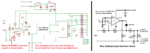
Your Eagle schematic is missing a dot where there is a connection in most places so it is confusing when a line crosses over or connects to another line.
I copied and pasted your pot into Paint then turned it 90 degrees so it is standing up awake instead of lying down sleeping. But instead I could have copied and pasted a pot from another schematic.
Its input is a microphone.
That is why my project is also powered from a rechargeable 9V Ni-MH battery.With a microphone as input, and with some calibration, it will be an effective sound pressure meter...
An attenuator is a resistor in series with the input (that you did not have) that feeds a resistor from the input to ground, making a voltage divider. The first schematic shows a series 10k feeding a 10k to ground that reduces the input voltage to half. If it did not attenuate enough it does not matter because the datasheet for the LM3915 shows a maximum allowed input of 35V. The maximum allowed input of the LM358 is only its supply voltage which will be 12V in your circuit.the first schematic on this topic I showed had a 10k resistor going to pin 5 of the Lm3915 and another 10k resistor from the same pin 5 going to GND and you said that was the attenuator so I assumed putting back those components in the circuit would be the attenuator if not then what is it that I should do to reduce the 56v. ( So what I did was the place them at the start of the peak detector circuit, and it seems that was wrong so how would I do it.)
This amplifler like many amplifiers has one of the two screw terminals as the amplifier's ground connection to the speaker. You must measure it to find which is the audio output terminal and which is the ground terminal. Some amplifiers have two signal outputs and I looked at the datasheet for the chip on the Chinese amplifier to see that it has only one output, not two.You asked why do I think the amplifier has two output, it has 2 screw terminals just like any other amplifier I have ever seen in my life that you connect 2 speaker wires to, so that connector with 2 screw terminals is where I planned to connect the vu meter and also the 2 wires from the speaker.
Like the LM358 dual opamp, the unused opamp must be properly disabled to prevent it from oscillating or overheating. Connect the output to the (-) input so it has a voltage gain of 1 then connect the (+) input to 0V.I keep using tl072 because I already have the chip if its a case where there will be a problem using it in the way I have it here then I would have to search for a tl071 as you said. ( so is it ok to use the tl072 or do I have to use a single opamp?)