Continue to Site

Welcome to EDAboard.com

Welcome to our site! EDAboard.com is an international Electronics Discussion Forum focused on EDA software, circuits, schematics, books, theory, papers, asic, pld, 8051, DSP, Network, RF, Analog Design, PCB, Service Manuals... and a whole lot more! To participate you need to register. Registration is free. Click here to register now.

[moved] led problem wont light up anymore

Status
Not open for further replies.

boomtheroom

Newbie level 6
Joined
Jan 26, 2017
Messages
13
Helped
0
Reputation
0
Reaction score
0
Trophy points
1
Activity points
92
hi all
i,m a newbie at the best of terms, i have just realized that my led on my motorcycle
normally glows when first turned on ignition is not working anymore , if i put my multi meter across the legs in diode test mode i get a reading of .010 v i get the buzz noise from my multi meter but led doesn't light up..what does this mean?
any help would be appreciated
 

Attachments

  • IMG_5148[1].jpg
    IMG_5148[1].jpg
    503.9 KB · Views: 117

What is your meter set for? Voltage or Resistance? A buzzing noise is usually reserved for continuity setting. So are you
sure you are not reading .010 Ohms and not Volts? Especially as you say the module is removed from the bike, there can be no voltage.

If it is ohms, you have a shorted LED. If you plug it in and it is supposed to be lit, and you have very little Voltage, (< a volt or even less), but other LED's are lit,
that verifys the short. An open LED will have a voltage of 3 or so volts across it.

"The LED or its driving circuit is shorted."
FYI: Not every failure in electronics is a "short". The majority are probably the exact opposite: Opens; connections or components that aren't connected anymore.
:thinker:
 
Last edited:

the multi meter is setup fro diode testing so .010v is showing with the beep
 

hmmm are you any good at looking at circuit boards and figuring out whats what?
 

hmmm are you any good at looking at circuit boards and figuring out whats what?
Not perhaps the most constrictive comment Boomtheroom, many of us here have been in research and develepment or industry for longer than transistors have been around, we know what we are talking about!

What we don't have is a schematic for your circuit board so we can only make guesses at what may be wrong based on information you provide. Please understand that how you measure components with a test meter will change the results you see. To measure a component, a test meter has to produce a voltage across its probes and monitor how much current flows between them and each different model of meter uses different voltages and different thresholds that start the buzzer. That's why we need more detailed information to be able to help you, we still don't know what your meter is telling you.

Usually, but not always, when testing on a 'diode' range, a meter tries to pass a fixed current across the probes and it returns the voltage it sees across them, its what we call the 'forward voltage' or 'Vf' of the diode when the polarity lets it conduct. However, it isn't foolproof, especially when measuring a component wired into a circuit like your LED because it can't tell if other components are influencing the reading. By far the most likely cause of your problem is the LED itself but it could for example have a capacitor across it that has failed with a short circuit. The meter can't tell which it is if they are connected together.

Your best option is to remove the LED from the board and test it in isolation, if it is faulty, a new one is very inexpensive. Make sure you note which way around the legs are, there is usually a flat edge on one side of the LED body to tell you the orientation. It will not light if wired backwards! If it isn't the LED at fault, you need to trace out the schematic around it to discover where its source of power comes from. There is no way we can do that for you I'm afraid, it is up to you to do it.

Brian.
 

sorry i wasnt trying to be rude ..i just meant can u tell by just looking at the image of a circuit and tell whats going on :->
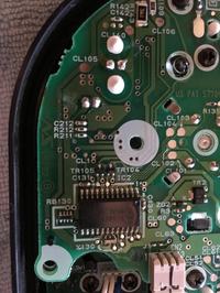
the led is the 2 solder joints above c212


i have a couple of questions you ll have to excuse my ignorance
if i put voltage directly on the led legs in circuit the led lights up ..by doing this could i damage the other components before the led in the circuit track ?seeing im not applying the voltage at the beginning of the circuit, effectively putting voltage at the end of the led circuit?
 

Hi,

by doing this could i damage the other components before the led in the circuit track ?
A LED need some current limiting to operate safely. Giving it a voltage wihtout limit could easily destroy the LED immedaitely.
And other parts, too.

Klaus
 

Klaus is telling you that an LED is a constant voltage device. You might find it easiest to think of it like a dam across a gorge. The height of the dam is the voltage needed for the LED to conduct and the flow of water over it's top is what makes the LED light up. If the water level is too low (not enough voltage) the water doesn't reach to top and nothing flows (LED not lit), if you try to raise the water level several metres above the dam height, you get an uncontrolled torrent and the dam gets washed away (LED fried). You need a method to limit the water height to keep it just gently oveflowing. What you did by wiring a voltage straight across the LED would be like raising the water level and you could have damaged it and the circuit driving it irrepairably.

On your device, the flow (the LED current) is almost certainly restricted to a safe level by a resistor in series with it. The picture isn't easy to follow but it looks like the left LED solder pad goes to a copper trace that goes to a via hole just beneath the last '1' of the R211 text. The track will continue from the other side of the hole on the back of the board, see if you can see where it leads to.

Bear in mind that we can only go on the information we have and the assumption that the LED is not lighting because of a fault in the LED circuitry. We are assuming the problem isn't in your motorcycle generator or wiring to it.

Brian.
 

I test LEDs with a 390 ohm resistor in series with a 9V battery. The resistor limits the current in a 1.7V red LED to (9V - 1.7V)/390 ohms= 18.7mA. The current in a 3.5V blue or white LED is (9V - 3.5V)/390 ohms= 14.1mA. The current is less when the battery voltage runs down but my Panasonic alkaline battery was made on the 90th day of 2004 or on the 4th day of 1990 and it still works fine.
 

I test LEDs with a 390 ohm resistor in series with a 9V battery...

If it is a bit old, it has got considerable internal resistance and you can safely forget the series resistor; these batteries are basically AAAA cells (six of them) in series. They are basically designed for low current and long life applications.

By the way, they get old fairly fast: I do not see the capacity mentioned on the package. The AA battery from varta (49 day or week of 2106 date of mfg) leaks profusely in the wireless keyboard and mouse.

- - - Updated - - -

if i put voltage directly on the led legs in circuit the led lights up ...

After all, the working circuit is going to apply some voltage across the legs of the LED; of course if you put more voltage, then it is very likely to get damaged. But as you have noticed, the LED lights up means it is working.

You need to dig further and see what is at fault.

Best way to pout voltage is using a multimeter in the diode mode; it will not put more than 3V or pass more than 5mA (usually; please read the manual). If the diode needs a higher forward voltage, it will show OL (again, this is common for most multimeters). The result will be same if you reverse bias the diode (no current flows).
 

ready 220ohms one way 330ohms the next way if that helps at all?
 

Hello boomtheroom,
I doubt the indicator LED is at fault. I'd say your problem lies further down and there's a good chance its the MLX10407 IC that may be causing the the failure of the LED to light up.
You need to trace back (with your multi-meter), to the appropriate pin on IC2. The LED may be driven by a SMD transistor, which in turn will be driven by one of the pins of IC2.
You'll have to see which of the above actually drives the LED.
Trouble-shooting the circuit will be almost be impossible without the whole cluster being powered up in its normal state. I'm not sure if you could power it with just 12 volts at the
appropriate points for it to operate without being connected to your motorbike. Though it would need feedback from the various sensors on your bike to operate fully.
Is there a possibility you could find out which wires go to where on your bike? As this may help in regards to at least being able to power up the unit without it having to be attached
to your bikes wiring loom.
Regards,
Relayer

P.S. Here is a link for IC2's datasheet:

MLX10107
 

Status
Not open for further replies.

Similar threads

Part and Inventory Search

Welcome to EDABoard.com

Sponsor

Back
Top