Continue to Site

Welcome to EDAboard.com

Welcome to our site! EDAboard.com is an international Electronics Discussion Forum focused on EDA software, circuits, schematics, books, theory, papers, asic, pld, 8051, DSP, Network, RF, Analog Design, PCB, Service Manuals... and a whole lot more! To participate you need to register. Registration is free. Click here to register now.

[Moved]: how to calculate the gate resistance of Igbt (fg25n120) /Mosfet

Status
Not open for further replies.
Re: NEED HELP ,how to calaculate the gate resistance of Igbt (fg25n120) /Mosfet

More gate resistor increases risetime / falltime but this is not
how you want to get dead time (i.e. nobody conducting).
You might end up with a by-the-50%-level "dead time" but
have a significant cross conduction.

As fast as the FET can take (drain dV/dt) is usually best
for overall switching losses, other than taking advantage
of soft switching perhaps - and this is more about phasing
than slew rate.
 

Re: NEED HELP ,how to calaculate the gate resistance of Igbt (fg25n120) /Mosfet

Thnkz Electrino N S,

Thnkz FvM,

i wish to use ir2110 driver ic or ir23364(d)

ir2110 ic can deliver 2A current..(Io+,Io- = 2A ,From datasheet).

http://www.irf.com/product-info/datasheets/data/ir2110.pdf

but it drive nly for half bridge.

for my applicationn

i wana to drive 3 phase inverter (IGBT FG25N120ANTD)

Ir23364(D) driver ic can drive 3 phase bridge.

**broken link removed**

but itz Io+ =200ma,Io- =350ma.

can i use ir23364(d) driver ic by increasing Rg

Rg = 15/.2 = 75 ohm.

dVs/dt = 50V/ns (Allowable VS offset supply transient relative to VSS , from datasheet). it will depend on rg.

dead time = 275ns (ir23364 ,datasheet)

is this dead time is enough for my application ??
or shall i add external dead time ??


can i use fast optocoupler ic 6N137 ???
Tlph = 45ns..

http://www.fairchildsemi.com/datasheets/HC/HCPL2631.pdf

SPWM Freq is 33khz .

Pls share your knowledges....


regards

mobin

you asked wether 275ns is enough dead time , the answer is that you should know from the calculation i gave u :

i=dQ/dt , we know that i=0.2A , and q= 200nC so t=200nC/0.2A=1us so , your IGBT needs 1us to turn on and 1us to turn off , so when u order the igbt to turn off it will take 1000ns but after 275ns of deadtime the other transistor in the half bridge will be ordered to turn ON , SO SHORT THROUGH WILL HAPPEN !!! THIS DEADTIME is NOT enough !!!!

use 3 IR2110 , to create a 3 phase bridge ,stop limiting your options because of this IC (ir23364)
if you are lazy and want a three phase driver : check out HIP4086 or A4915

regards
 
Re: NEED HELP ,how to calaculate the gate resistance of Igbt (fg25n120) /Mosfet

you asked wether 275ns is enough dead time , the answer is that you should know from the calculation i gave u :

i=dQ/dt , we know that i=0.2A , and q= 200nC so t=200nC/0.2A=1us so , your IGBT needs 1us to turn on and 1us to turn off , so when u order the igbt to turn off it will take 1000ns but after 275ns of deadtime the other transistor in the half bridge will be ordered to turn ON , SO SHORT THROUGH WILL HAPPEN !!! THIS DEADTIME is NOT enough !!!!

use 3 IR2110 , to create a 3 phase bridge ,stop limiting your options because of this IC (ir23364)
if you are lazy and want a three phase driver : check out HIP4086 or A4915

regards

Thnkz Electro NS,

i found an App note for Calculating dead time in IGBT module by infineon

https://www.infineon.com/dgdl/Infin...n.pdf?fileId=db3a30431a5c32f2011a5daefc41005b

In this APP note

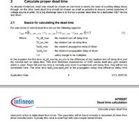
an eqn for calculating dead time


should i use this eqn ??

regards

mobin
 

Re: NEED HELP ,how to calaculate the gate resistance of Igbt (fg25n120) /Mosfet

Thnkz Electro NS,

i found an App note for Calculating dead time in IGBT module by infineon

https://www.infineon.com/dgdl/Infin...n.pdf?fileId=db3a30431a5c32f2011a5daefc41005b

In this APP note

an eqn for calculating dead time


should i use this eqn ??

regards

mobin

yes offcourse it might work i makes a lot of sense , but the terms turn off donot take into account the drive current (he mension something about external gate resistor) so the writer presumes results from oscilloscope measurements maybe ?? , i want you to do this calculation and compare it to the calculation i gave u then we can discuss , if the results are not close , right ??

good luck
 
Re: NEED HELP ,how to calaculate the gate resistance of Igbt (fg25n120) /Mosfet

yes offcourse it might work i makes a lot of sense , but the terms turn off donot take into account the drive current (he mension something about external gate resistor) so the writer presumes results from oscilloscope measurements maybe ?? , i want you to do this calculation and compare it to the calculation i gave u then we can discuss , if the results are not close , right ??

good luck

Thnkz electrino N S

I did calculation ,pls check

Td(on) = 50ns & Td(off) = 190ns (at 25deg c, Rg = 10ohm, Ic =25A ..Values from datasheet.)

i noted that the chara of switching time(Td(on) & Td(off) ) Depend on external gate resistance and collector current.
in my application collector current is below 5Amp. and Rg = 27ohm(calculate by Electrino in previous post).

also Tr,Tf is not considerd.Tr= 60ns,Tf=100ns.

as per Eqn

the first term Tdoff - Tdon = 140ns.

second term is the parameter delay match in IR2110 driver datasheet = 10ns

so total = 150ns * 1.2 = 180ns.

also i attached the switching chara.

from graph, When Rg = 27 ohm( 25-30),Ic = 25A approximate value of Tdon = 65ns,Toff =275ns
Tdoff - Tdon = 210ns
delay mismatch is 10ns
so dead time is 220*1.2 =264ns

is this calculation is right??
Tonpdd = 160ns, Toff pdd = 150ns (ir2110 datasheet)


should i consider the propgation delay of optocoupler ic 6n137, which isolate cntrl ckt from driver ic ??

regards
mobin
 

Attachments

  • DELAYY.jpg
    DELAYY.jpg
    193 KB · Views: 89
  • toff.jpg
    toff.jpg
    142 KB · Views: 71
  • TON.png
    TON.png
    122.5 KB · Views: 86
  • TON TOF CURRENT.jpg
    TON TOF CURRENT.jpg
    162 KB · Views: 81

Re: NEED HELP ,how to calaculate the gate resistance of Igbt (fg25n120) /Mosfet

Thnkz electrino N S

I did calculation ,pls check

Td(on) = 50ns & Td(off) = 190ns (at 25deg c, Rg = 10ohm, Ic =25A ..Values from datasheet.)

i noted that the chara of switching time(Td(on) & Td(off) ) Depend on external gate resistance and collector current.
in my application collector current is below 5Amp. and Rg = 27ohm(calculate by Electrino in previous post).

also Tr,Tf is not considerd.Tr= 60ns,Tf=100ns.

as per Eqn

the first term Tdoff - Tdon = 140ns.

second term is the parameter delay match in IR2110 driver datasheet = 10ns

so total = 150ns * 1.2 = 180ns.

also i attached the switching chara.

from graph, When Rg = 27 ohm( 25-30),Ic = 25A approximate value of Tdon = 65ns,Toff =275ns
Tdoff - Tdon = 210ns
delay mismatch is 10ns
so dead time is 220*1.2 =264ns

is this calculation is right??
Tonpdd = 160ns, Toff pdd = 150ns (ir2110 datasheet)


should i consider the propgation delay of optocoupler ic 6n137, which isolate cntrl ckt from driver ic ??

regards
mobin

Bravo good calculation ,
regarding the propogation delay of opto couplers , usually you either use a fast optocoupler or follow that optocoupler with a totem pole or something similar to make the signal sharper .
i really cannot tell if it will affect you since it is delaying both signals and this has to do with the input logic circuit of the mosfet driver , which will tell when it reads a 1 or 0 .
so you might have to test or use a component between opto and driver to make signals look like square waves again .
 
Re: NEED HELP ,how to calaculate the gate resistance of Igbt (fg25n120) /Mosfet

should i consider the propgation delay of optocoupler ic 6n137, which isolate cntrl ckt from driver ic ??
Basically yes. You should add it's maximum delay skew to the dead time to be on the save side.
 
Re: NEED HELP ,how to calaculate the gate resistance of Igbt (fg25n120) /Mosfet

Thnks frnds..

nw i wan to calculate the propgation delay of the optcoupler 6n137.

both TPHL & TPLH is same = 75ns from datasheet.

so TPHL- TPLH = 0

it has no significance in dead time.

also it depends on RL (350 ohm,1 K,4 K)

Also now i try to design the optocoupler ckt.

first part is interfacing optocoupler with control ckt

2 ways to connect..

pin2 is connected to 5v,
pin3 is connected to output of AND gate(cntrler ckt)through series resistor.

or

Pin 2 is connected to out of and gate and
pin3 is connected to grnd through series resistor.

design of series resistor

If = 10ma,Vf = 1.4v

logic input supply voltage 5v

R = (5-1.4)/10ma =360ohm
STD value is 390 ohm or 470 ohm.

is this right calculation??

should i consider IFL,IHL(INPUT CURRENT HIGH LEVEL,LOW LEVEL) in datsheet ??

which connection is used ?

regards

mobin
 

Re: NEED HELP ,how to calaculate the gate resistance of Igbt (fg25n120) /Mosfet

2 ways to connect..

pin2 is connected to 5v,
pin3 is connected to output of AND gate(cntrler ckt)through series resistor.

or

Pin 2 is connected to out of and gate and
pin3 is connected to grnd through series resistor.

6N137 has its output inverted. If you want to keep your uC signal non inverted, use the first connection variant (which is also an inverting circuit).
 

Re: NEED HELP ,how to calaculate the gate resistance of Igbt (fg25n120) /Mosfet

is design value of R = 390ohm is enough??

next am trying to design the interface optocoupler b/w driver ic Ir2110 .

pin 8 vcc is connected to 15 v supply through series resistor R2.

Vcc of 6n137 is 5V frm datasheet.

https://www.fairchildsemi.com/datasheets/6N/6N137.pdf

vlotage drop across resistor is 15 - 5v = 10v.

R2 = V/I

cant find the supply current I in datasheet .

is ICCH, ICCL is supply current ??

should i connect the pin 7 Venable to vcc ?? or jus float ??

pin 6 Vout is pull up to 15 vc ??

pull up resistor value ?? 1k ohm??

input bias current for ir2110 is 20uA. When VDD = 15V

- - - Updated - - -

is design value of R = 390ohm is enough??

next am trying to design the interface optocoupler b/w driver ic Ir2110 .

pin 8 vcc is connected to 15 v supply through series resistor R2.

Vcc of 6n137 is 5V frm datasheet.

https://www.fairchildsemi.com/datasheets/6N/6N137.pdf

vlotage drop across resistor is 15 - 5v = 10v.

R2 = V/I

cant find the supply current I in datasheet .

is ICCH, ICCL is supply current ??

should i connect the pin 7 Venable to vcc ?? or jus float ??

pin 6 Vout is pull up to 15 vc ??

pull up resistor value ?? 1k ohm??

input bias current for ir2110 is 20uA. When VDD = 15V
 

Re: NEED HELP ,how to calaculate the gate resistance of Igbt (fg25n120) /Mosfet

You better use a small current series regulator (78L05) or a 5.1V zenner for 6N137 supply. The recommended voltage is 4.5V - 5.5V but the absolute maximum allowed voltage is 7V so any spike from 15V driver power supply could destroy it.

The supply current is indeed ICCL/ICCH (around 10mA).

The ENABLE pin 7 has already a pull-up resistor so it could be left open.

A pull-up resistor of 1K for the open collector output is OK. The pull-up resistor could be connected to 15V, along with the logic power supply of IR2110 (which is 20V maximum).

Don't forget the decoupling capacitors for 6N137 and IR2110.
 

Re: NEED HELP ,how to calaculate the gate resistance of Igbt (fg25n120) /Mosfet

input bias current for driver ic ir2110 is 20uA , When Vin = VDD =15V

the output of pull up resistor is 1k connected to 15v

Vcc of 6n137 is 5v.
gnd is common with Vss & Com pins of IR2110

input bias current is 15/1k = 15ma ..

is it destroy ir2110 ic ??
 

Re: NEED HELP ,how to calaculate the gate resistance of Igbt (fg25n120) /Mosfet

Thanks alot sir .
Sir should i connect 6n137 like this ?
pin 1 , 4 --> Not connected
pin 2 --- > (anode ) 5v ( cntrlr supply)
pin3 --- > ( cathode ) connected to uc with 390ohm series resistor

pin 8 --- > 5 V ( 7805 Regulated supply)
pin 7 ----> NC
pin 6 --- > output (with 1 k resistor Connected to 15 v power supply for VDD & VCC of IR2110)
pin 5 --- > Grounded (COmmon with VSS & Com PINS of Ir2110)

should i connect .1uf across pin 8 vcc and pin 5 grnd of 6n137 ?
plz reply
 

Re: NEED HELP ,how to calaculate the gate resistance of Igbt (fg25n120) /Mosfet

Yes, everything it's ok.
 

Re: NEED HELP ,how to calaculate the gate resistance of Igbt (fg25n120) /Mosfet

Thnks red alert.

1 doubt remaining..

in datasheet perfomance curves like , pulse width distortion, tr,tf, propgation delay etc depend on Rl
350 ohm, 1k, 4k.

can i use 390 ohm as pull up resistor insted of 1k ????
pull up resistor is connected to 15v ( power supply for driver ic , vdd,vcc pins of ir2110)

pls relply
 

Re: NEED HELP ,how to calaculate the gate resistance of Igbt (fg25n120) /Mosfet

The datasheet performance curves correspond to a Vcc = 5V. Your Vcc is triple so the similar performances could be aquired for a x3 pull-up resistor.

390 x 3 = 1.17 Kohm so a value of 1K it's just fine.

- - - Updated - - -

Your Vcc is still 5V but they have connected the pull-up resistor to 5V, too (look at the test circuit from the datasheet).

You're connecting the pull-up resistor to 15V so for the same output current, the resistor should be three times higher.
 

Re: NEED HELP ,how to calaculate the gate resistance of Igbt (fg25n120) /Mosfet

Thnkz..

sorrry.

i didn t noticed pull up resistor to 5 v.

my power supply is designed by

trnsfmr>> 230/15v
full bridge rectifer using 1n4007.
filter capacitor 100uf
now output voltage is 21.7v
then i connect 7815 across the capacitor,
also i connected 100uf capacitor across the output of 7815
1n4007 diode cathode connected to 7815 IN & ANODE Connected to OUT of 7815.

output of 7815 is 15.43v

is this design is good ??
any changes ?? filter capacitor value ?? 1000uf???

can i connect 7805 to the output of 7815 to get 5v supply to 6n137 ??

or

connect a resistor to 15 v to vcc of 6n137

R = 15-5/10ma =1K

regards

mobin
 

Re: NEED HELP ,how to calaculate the gate resistance of Igbt (fg25n120) /Mosfet

Yes, the filter capacitor could be a little bit bigger (470uF - 1000uF).

If the 15V power supply is well stabilised (and it is) you could use a simple series resistor for the 6N137 supply. That series resistor and the optocoupler decoupling capacitor act like a low-pass filter thus avoiding any parasitic spikes.

Anyway, you should connect that resistor as close to 7815 output, to avoid current sharing with the driver through the same wire.

Beware of ground loops, too. Any spikes at optocoupler input/supply could lead to parasitic MOSFET/IGBTs turn-on.
 

Re: NEED HELP ,how to calaculate the gate resistance of Igbt (fg25n120) /Mosfet

Thnkzz...

can i connect 7805 to the output of 7815 to get regulated supply ??

- - - Updated - - -

should i connect zener diode across gate - emiter of igbt to protect from over voltage ??
 

Status
Not open for further replies.

Part and Inventory Search

Welcome to EDABoard.com

Sponsor

Back
Top