Continue to Site

Welcome to EDAboard.com

Welcome to our site! EDAboard.com is an international Electronics Discussion Forum focused on EDA software, circuits, schematics, books, theory, papers, asic, pld, 8051, DSP, Network, RF, Analog Design, PCB, Service Manuals... and a whole lot more! To participate you need to register. Registration is free. Click here to register now.

[Moved]: how to calculate the gate resistance of Igbt (fg25n120) /Mosfet

Status
Not open for further replies.

mobinmk

Full Member level 2
Full Member level 2
Joined
May 27, 2010
Messages
140
Helped
4
Reputation
8
Reaction score
4
Trophy points
1,298
Location
Kollam (Quilon),kerala, India
Visit site
Activity points
2,484
Hi frndz.

i tried to find the exact answer to design the gate resistance in websites around 2 mnth.
i cant find.

gate resistance depend on??

spwm frequency is 33khz.

plz share your knowledges..


regardz
 

Re: NEED HELP ,how to calaculate the gate resistance of Igbt (fg25n120) /Mosfet

Hello mobinmk,

You could have the worst capacitance value, in this case Cies = 2700pF.
Then you can calculate the "Gate impedance" with the capacitive reactance formula:

In it case: 1 / (2.Pi.Freq.C) => 1 / (6.28 x 33000Hz x 2700pF) = 1787 Ohms

I hope you can solve your question.

Have a nice day.

Best regards,
Juan_zo

Thnkz Juan ,

i hav some doubts

DATASHEET

https://www.fairchildsemi.com/datasheets/FG/FGA25N120ANTD.pdf

in datasheet Cies = 3700pf [test condition - VCE = 30 V, VGE = 0 V, f = 1 MHz ]

in this case f=33khz

GATE IMPEDANCE = 1 / (2.Pi.Freq.C) => 1 / (6.28 x 33000Hz x 2700pF) 1 / (2.Pi.Freq.C) => 1 / (6.28 x 33000Hz x 3700pF) =1304 Ohms .

standard value of resistor available is 1.2k & 1.5k .
1) can i use 1.5k ??

2) is gate resistance depend on Ton OR TOF time??

3) is it connect diode (reverse bias) across gate resistance ??

4) Is 3700 pf @ 1Mhz ???[test condition]

is 2700 pf @ 33khz???

dc link voltage is 600v

driver ic ir2110.

ir2110 vcc is 16v
so HO,LO is 12-13v,

5) is 12V sufficent to drive FGA25N12O IGBT??

In websites MIN 15 OR 16V to drive igbt and switching frequency is below 20khz.

6) is 33khz SPWM frequency is compatable for FGA25N120 IGBT ??

7) is 10k resistor is connected across EMITTER AND GATE OF IGBT ??

i think itz used to avoid unexpected turn on turn off due to miller capacitence .


Regardz

Mobin
 
Last edited:

Re: NEED HELP ,how to calaculate the gate resistance of Igbt (fg25n120) /Mosfet

You are welcome Mobin!

About you questions:

1,2) Your transistor you have to Calculated impedance of 1304 ohms , but the Rg needs to charge and discharge the Cgd Cge and fast , to limit generator 's current and to Prevent auto- oscillations too . I have some formulas, I think you can check them , however I , in transistor 's datasheet some values ​​do not Appear , values ​​like Lg . How to do then? Well , They Often use low value resistor, around of 1 to 20 Ohms to drive IGBTs . If you look in your transistor datasheet , They used 10 Ohms . Here you have everything Explained if want to read .
3) You could protect IGBT's gate of higher and lower voltages than +-20V, I think it is better if you connect two 18V zenners opposite between gate to ground.
4) Mmm, how to explain it? Well capacitance is a phisic parameter and it depends on distances and dielectric materials, in the transistor, some values change for the voltages applied in its terminals, however, I think you could assume the capacitances are similar for all frequencies if only have 1 frequency test.
5) Yes, the typical value is 5.5V for On state, if you use higher values you can define better the On and Off status with a square wave, remember than +-20 is the Vge maximun voltage.
6) Yes, it is not a problem with square wave, it works at 2.5MHz max.
7) Yes, you can use 10K across gate an emitter, if you want to sure the non-auto On, you can use 1K.

I hope I could help you.

Best regards,
Juan

- - - Updated - - -

http://www.efo-power.ru/BROSHURES_CATALOGS/AN-1001_IGBT_and_MOSFET_Drivers_Correctly_Calculated.pdf
 
Last edited by a moderator:
Re: NEED HELP ,how to calaculate the gate resistance of Igbt (fg25n120) /Mosfet

You are welcome Mobin!

About you questions:

1,2) Your transistor you have to Calculated impedance of 1304 ohms , but the Rg needs to charge and discharge the Cgd Cge and fast , to limit generator 's current and to Prevent auto- oscillations too . I have some formulas, I think you can check them , however I , in transistor 's datasheet some values ​​do not Appear , values ​​like Lg . How to do then? Well , They Often use low value resistor, around of 1 to 20 Ohms to drive IGBTs . If you look in your transistor datasheet , They used 10 Ohms . Here you have everything Explained if want to read .
3) You could protect IGBT's gate of higher and lower voltages than +-20V, I think it is better if you connect two 18V zenners opposite between gate to ground.
4) Mmm, how to explain it? Well capacitance is a phisic parameter and it depends on distances and dielectric materials, in the transistor, some values change for the voltages applied in its terminals, however, I think you could assume the capacitances are similar for all frequencies if only have 1 frequency test.
5) Yes, the typical value is 5.5V for On state, if you use higher values you can define better the On and Off status with a square wave, remember than +-20 is the Vge maximun voltage.
6) Yes, it is not a problem with square wave, it works at 2.5MHz max.
7) Yes, you can use 10K across gate an emitter, if you want to sure the non-auto On, you can use 1K.

I hope I could help you.

Best regards,
Juan

- - - Updated - - -

http://www.efo-power.ru/BROSHURES_CATALOGS/AN-1001_IGBT_and_MOSFET_Drivers_Correctly_Calculated.pdf

Thnkz Juan_zo..

in 2nd ques

i mean
1234.png

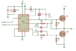
is diode d2, d3 DISCHARGE the gate capacitances of the IGBT quickly, bypassing the gate resistors, reducing the turn off time. R1 and R2 are the gate current-limiting resistors. ??

Can i connect UF5408 DIODE antiparellel across collector and emitter of FGA25N120 IGBT ??


Regardz

Mobin
 

Re: NEED HELP ,how to calaculate the gate resistance of Igbt (fg25n120) /Mosfet

Unfortunately I have to disagree with many answers given by juan_zo.

Most severe the Rg calculation, also the statement about acceptable FGA25N120 switching frequency.

The FGA25N120 datasheet shows switching times for a Rg range of 5 to 70 ohms which can serve as a ballpark figure. Higher values will cause respective switching losses. I would go for the upper range, e.g. 30 to 50 ohm in a first attempt.

33 kHz is quite high as IGBT switching frequency and would usually demand a power reduction.

Can i connect UF5408 DIODE antiparellel across collector and emitter of FGA25N120 IGBT ??
What should be the purpose of paralleling a small 3A diode to a 25 A rated internal IGBT diode?
 
Re: NEED HELP ,how to calaculate the gate resistance of Igbt (fg25n120) /Mosfet

Dear Mobin,

Yes, you are right about d1, d2 (they discharge faster Cgs and Cgd to source) and R1, R2 limit corrent and.
About UF5408 between Collector and Emitter, please, check the code after 120 (generally it code has letters like: A, AN, AND, ANTD), if you have FGA25N120A, FGA25N120AN they have not damper diode, then you must add an external diode on it if you will use inductive loads. If you have FGA25N120ANTD, FGA25N120ANTDTU, FGA25N120ANTD_07, FGA25N120ANTD_F109 they have an internal damper diode, then it is not necesary an external diode.

Have a nice day.

Best regads,
Juan
 
Re: NEED HELP ,how to calaculate the gate resistance of Igbt (fg25n120) /Mosfet

if you have FGA25N120A, FGA25N120AN they have not damper diode, then you must add an external diode
Fairchildsemi offers FGA25N120ANTD and FGA25N120ANTDTU, both have an internal diode. Where do you see a FGA25N120 bersion without diode?
 
Re: NEED HELP ,how to calaculate the gate resistance of Igbt (fg25n120) /Mosfet

Here you have the FGA25N120AN datasheet
Thanks, I see. But this part has been apparently obsololeted by Fairchildsemi since many years. They only make the "D" versions.
 
Re: NEED HELP ,how to calaculate the gate resistance of Igbt (fg25n120) /Mosfet

Dear FvM,

You are welcome.

Have a nice day.

Best regads,
Juan
 

Re: NEED HELP ,how to calaculate the gate resistance of Igbt (fg25n120) /Mosfet

Thnkz Fvm

i found in some websites, the h bridge ckt diagram
an extra fast recovery diode is connected across the collector and emitter of igbt.
thus am confused

regardz

mobin
 

Re: NEED HELP ,how to calaculate the gate resistance of Igbt (fg25n120) /Mosfet

Anti-parallel diodes are required for all IGBT bridge circuits with inductive load if they aren't already built-in with the IGBT.

They must be rated for full load current. Connecting a second external diode parallel to an internal diode is effectively useless.
 
Re: NEED HELP ,how to calaculate the gate resistance of Igbt (fg25n120) /Mosfet

Dear Mobin,

Yes, you are right about d1, d2 (they discharge faster Cgs and Cgd to source) and R1, R2 limit corrent and.
About UF5408 between Collector and Emitter, please, check the code after 120 (generally it code has letters like: A, AN, AND, ANTD), if you have FGA25N120A, FGA25N120AN they have not damper diode, then you must add an external diode on it if you will use inductive loads. If you have FGA25N120ANTD, FGA25N120ANTDTU, FGA25N120ANTD_07, FGA25N120ANTD_F109 they have an internal damper diode, then it is not necesary an external diode.

Have a nice day.

Best regads,
Juan
Thnkz FVM,

Thnkz JUAN_ZO

i use FGA25N120ANTD igbt. i wana to drive 3 phase induction motor (1/4 hp), I < 1A,415V.
it have internal damper diode. so no need of external diode

nw i am confused..after the post #6. by Fvm

Unfortunately I have to disagree with many answers given by juan_zo.

Most severe the Rg calculation, also the statement about acceptable FGA25N120 switching frequency.

The FGA25N120 datasheet shows switching times for a Rg range of 5 to 70 ohms which can serve as a ballpark figure. Higher values will cause respective switching losses. I would go for the upper range, e.g. 30 to 50 ohm in a first attempt.

Any eqn available to calculate exact RG??
in some tutorials i find two resistors
Rg on &Rg off . they are connected in parallel.


regards

mobin
 

Attachments

  • gateprtct.jpg
    gateprtct.jpg
    78.4 KB · Views: 317
Last edited:

Re: NEED HELP ,how to calaculate the gate resistance of Igbt (fg25n120) /Mosfet

If you look at AC current amplitude vs a fixed amplitude input
sinusoid at varying frequency (with everything but gate tied
to ground, and gate DC-biased into inversion) you should see
that the current/frequency curve has two regions - one that
is proportional to frequency (Cgg) and one that is constant(ish)
(Rg). The flat region ought to give you Rg as Vsin/Isin at those
points. I would assume you won't go out far enough in frequency
to start seeing the inductance roll on with a 1/f current/freq
slope.

Now looking at later replies it seems you want to figure an
external resistor. This is usually about controlling the drain
slew rate for soft(er) switching. I am not sure the IGBT acts
the same as a MOSFET because the input is not as intimately
coupled to the output (Cdg).

I think this may just want some bench work. Try resistors from
(say) 1 to 1K by half decades with a pulsed gate drive and observe
the drain slew slope with an appropriate (to the input pulse width
and drain supply voltage) inductor load. I suspect you won't see
the same linear-ish drain dV/dt slope as a power MOSFET, but
you may see a sweet spot that you like.
 

Re: NEED HELP ,how to calaculate the gate resistance of Igbt (fg25n120) /Mosfet

Dear Juan-zo.

i read the application note

http://www.efo-power.ru/BROSHURES_CATALOGS/AN-1001_IGBT_and_MOSFET_Drivers_Correctly_Calculated.pdf

Nw am trying to calculate Rg for igbt FGA25N120DANT.

am using to drive igbt by driver ic IRS23364, PLCC PACKAGE, it have integrated bootstrap ckt

Datasheet.

**broken link removed**

Io+ & I o- (typical) 200 mA & 350 mA
tON & tOFF (typical) 530 ns & 530 ns
Deadtime (typical) 275 ns

i wan to make 3 phase inverter, high side igbt is drive by bootsrap circuit, it will depend on the voltage between Vb and Vs.

Vbsuv+(under voltage lock out) = 11.6v,

for designing take it as 12v.

As per application note
http://www.efo-power.ru/BROSHURES_CATALOGS/AN-1001_IGBT_and_MOSFET_Drivers_Correctly_Calculated.pdf

First calculate drive power.

Eqn is

Pdrv =Qg * Fin * ΔVgate

Qg - total gate charge = 200nC @ (VCE = 600 V, IC = 25 A, VGE = 15 V )

F in = 33khz( switching frequency ,spwm)

ΔVgate = 15v - 0v =15v

So
Pdrv =200nc*33khz * 15

= 0.099w

Is it right ?

2 )can u explain non resonant driver??

3)is the 2nd eqn is applicable nly for non resonant driver??

should i use 2nd eqn in app note. ??

next

i check the value of Qg Vs Vge
qg.jpg

for vcc = 600v, vge = 15v,

Qg is 200nC.

Is it right ??

4) Should i use eqn 3 to calculate Qg ??

i skip this eqn 3 & move to eqn 4.

itz jus Ohms law.

I =V/R

Frm datsheet (IRS23364)

Io+ Output high short circuit pulsed current 120ma (typ) 200(max) —VO=0 V,VIN=0 V,PW ≤ 10 µs

Io- Output low short circuit pulsed current 250ma(typ) 350ma(typ) —VO=15 V,VIN=5 V,PW ≤ 10 µs

5) which value will take for I?? Io+ or I-??

I take it Io+ 120ma .

thus Rg is 15/120ma =125 ohm.

is it right??

Rg will depend on Ton & Toff time( bcz it limit current to charge Cge ,Ccg )

if Rg increases switching loss also increases..per.jpg


in datasheet the Rg value upto 70 ohm nly.

thus I = 15/70 =214ma.

6 ) should i add internal gate impedance 1034 ohm to external Rg ??

Am waiting for you reply.

regards

mobin
 

Re: NEED HELP ,how to calaculate the gate resistance of Igbt (fg25n120) /Mosfet

Hi Frndzz

is this Rg depends on dV/dt ??
dv/dt = 5v/ns..

Vcc - Vplateu
R = ----------------
Cres * dv/dt

cant find the plateu voltage in fg25n120 datsheet. ??

any other method to find rg with respect to dv/dt.

if i use driver ic ir2110 , itz output peak current 2A

VCC =15V

Rg internal =1304 ohm (calculate in #3)

let Rg ext = 47 ohm (Fvm recommend 30 - 50 ohm in post #6)

Rg total = 1351 ohm

I = VCC/Rg tot

I =11 ma

is this calculation is right ??


regards

mobin
 

Re: NEED HELP ,how to calaculate the gate resistance of Igbt (fg25n120) /Mosfet

no it isn't ,

i will try to explain this as best as i can , i no expert , so please donot judge

Rg role is to limit gate driver current to mosfet gate , the current control has fast the turn on/off of mosfet or IGBT

So start by : swithing frequency :33khz , the rise fall time should be a maximum of 1% to avoid short through (one igbt is turning On while the is turning off)
so (1/33khz )/100= 300ns
so we need to charge the ibgt gate on and off during this time , i=dQ/dt , i=200nC(gate charge)/300ns=0.6A

then we need 0.6A from the driver , the supply is 15v . Then Rg=15v/0.6A= 25ohm

hope this helps
 
Re: NEED HELP ,how to calaculate the gate resistance of Igbt (fg25n120) /Mosfet

The Rg internal calculation is erroneous from the start. It has been introduced by juan_zo in post #2, but it's no commonly known (or somehow useful) calculation method as far as I'm aware of.
 
Re: NEED HELP ,how to calaculate the gate resistance of Igbt (fg25n120) /Mosfet

Thnkz Electrino N S,

Thnkz FvM,

i wish to use ir2110 driver ic or ir23364(d)

ir2110 ic can deliver 2A current..(Io+,Io- = 2A ,From datasheet).

http://www.irf.com/product-info/datasheets/data/ir2110.pdf

but it drive nly for half bridge.

for my applicationn

i wana to drive 3 phase inverter (IGBT FG25N120ANTD)

Ir23364(D) driver ic can drive 3 phase bridge.

**broken link removed**

but itz Io+ =200ma,Io- =350ma.

can i use ir23364(d) driver ic by increasing Rg

Rg = 15/.2 = 75 ohm.

dVs/dt = 50V/ns (Allowable VS offset supply transient relative to VSS , from datasheet). it will depend on rg.

dead time = 275ns (ir23364 ,datasheet)

is this dead time is enough for my application ??
or shall i add external dead time ??


can i use fast optocoupler ic 6N137 ???
Tlph = 45ns..

http://www.fairchildsemi.com/datasheets/HC/HCPL2631.pdf

SPWM Freq is 33khz .

Pls share your knowledges....


regards

mobin
 

Status
Not open for further replies.

Part and Inventory Search

Welcome to EDABoard.com

Sponsor

Back
Top