phenol
Junior Member level 1
hi

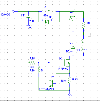
The design intent--switch RL /200-600 ohms of equivalent resistance/ off of 350vdc to gnd with a mosfet acting like a low side switch and provide short circuit protection. the output of the source has total bulk capacitance of 200uF low esr capacitors
Ive added diode clamped series inductors as shown to limit di/dt during aa short circuit event, tried 5-10uH airwound to avoid core saturation and also 47uH on ferrite, not much improvement; at voltages low enough - up to 200V-a dead short on the output (a very brief one, couple of ms, just quickly shorting the load terminals with a very short piece of wire) turns on the bipolar device and short circuit current is limited, effectively dumping the entire output voltage on the fet. it tends to heat up quickly, but it stays intact as long as the short is removed in due time. it works every time i short the output.
But if i ramp up the voltage to say 300V, shorting the output briefly still results in current limiting sometimes, but other times a loud spark occurs and the mosfet is smoked. the transient event triggers the slow acting overcurrent protection of the 300v source. Im at a loss to understand why the bipolar transistor between the gate and gnd fails to decrease the inrush current in the fet in time under higher voltage conditions when it seems to work reliably at 200v. In the few occasions it does work at 300v, the resulting spark during the short is minimal as the current is quickly limited as defined by the source resistor...but as something fails, the spark is rather loud and G ends up shorted to the drain as a result of which the bipolar device is blown, too.
the bipolar transistor is supposed to provide fast acting current limiting until the slower primary overcurrent protection is triggered a few ms later and power is removed, thus protecting the mosfet switch from overheating
im not in the right mood for blowing another dozen of mosfets (tried various parts, 500-800V, RDSon=200-500mohms), so im seeking advice here.
thanks
phenol