Continue to Site

Welcome to EDAboard.com

Welcome to our site! EDAboard.com is an international Electronics Discussion Forum focused on EDA software, circuits, schematics, books, theory, papers, asic, pld, 8051, DSP, Network, RF, Analog Design, PCB, Service Manuals... and a whole lot more! To participate you need to register. Registration is free. Click here to register now.

[SOLVED] MOSFET HV switch short circuit behaviour

Status
Not open for further replies.

phenol

Junior Member level 1
Joined
Oct 4, 2012
Messages
17
Helped
1
Reputation
2
Reaction score
1
Trophy points
1,283
Activity points
1,471
hi
8636646100_1349384206.png

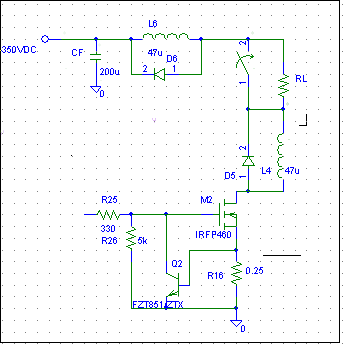
The design intent--switch RL /200-600 ohms of equivalent resistance/ off of 350vdc to gnd with a mosfet acting like a low side switch and provide short circuit protection. the output of the source has total bulk capacitance of 200uF low esr capacitors
Ive added diode clamped series inductors as shown to limit di/dt during aa short circuit event, tried 5-10uH airwound to avoid core saturation and also 47uH on ferrite, not much improvement; at voltages low enough - up to 200V-a dead short on the output (a very brief one, couple of ms, just quickly shorting the load terminals with a very short piece of wire) turns on the bipolar device and short circuit current is limited, effectively dumping the entire output voltage on the fet. it tends to heat up quickly, but it stays intact as long as the short is removed in due time. it works every time i short the output.
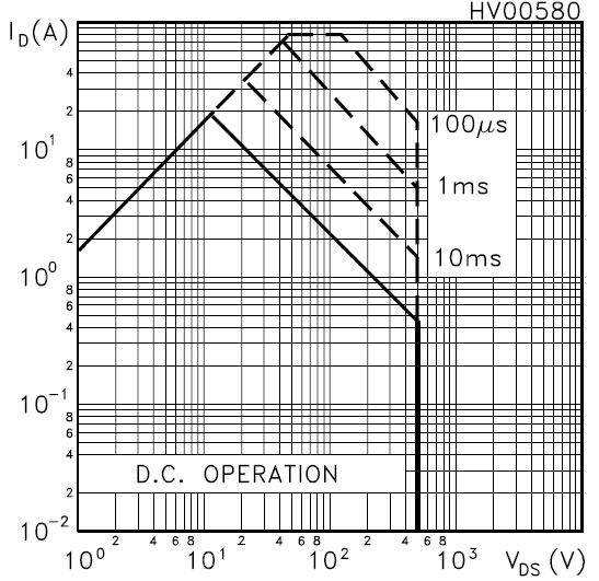
But if i ramp up the voltage to say 300V, shorting the output briefly still results in current limiting sometimes, but other times a loud spark occurs and the mosfet is smoked. the transient event triggers the slow acting overcurrent protection of the 300v source. Im at a loss to understand why the bipolar transistor between the gate and gnd fails to decrease the inrush current in the fet in time under higher voltage conditions when it seems to work reliably at 200v. In the few occasions it does work at 300v, the resulting spark during the short is minimal as the current is quickly limited as defined by the source resistor...but as something fails, the spark is rather loud and G ends up shorted to the drain as a result of which the bipolar device is blown, too.
the bipolar transistor is supposed to provide fast acting current limiting until the slower primary overcurrent protection is triggered a few ms later and power is removed, thus protecting the mosfet switch from overheating

im not in the right mood for blowing another dozen of mosfets (tried various parts, 500-800V, RDSon=200-500mohms), so im seeking advice here.

thanks
phenol
 

The current limiter circuit forces the FET into linear operation. If the pulse energy dissipated by the FET before supply shutdown exceeds the SOA, the transistor will be damaged. As the capacitor is storing 9 Ws at 300 V, the transistor seems to be predestinated to damage.

You may want to clarify the exact control sequence and expectected current waveform.
 

Dear,
The above Scheme seems to me a part of H-Bridge .. in my opinion the way you are implementing a short circuit protection with just a Bipolar transistor and a shunt resistor may not be adequate..as this type of scheme will result in the gate drive not going to low level instantly..but may result in ringing type waveforms at mosfet gate.. this can be understood by a simple example..suppose the output gets shorted..resulting in high currents ..these currents will result a voltage across Rsense..and as soon as these voltages goes above 0.6~0.7 Vdc..the transistor will conduct and will sink the gate drive..to switch off the mosfet..but this phenomena will not be a perfect one because the instance the mosfet will loose its drive at the same time current will start decaying which will ultimately result in transistor getting OFF again...which again will result in Mosfet conduction.. so this all cycle repeat..and due to this only you are encountering a rise in mosfet temperature.. this all is not blowing the Mosfet when High Volt DC bus is at 200VDC..because the charge at High volt DC BUS Capacitor is limited..but when same capacitor is charged to 300 Vdc..in that case mosfet blows because the above mentioned phenomena time constant will be large..and the Mosfet wil be under more stress due to more charge on the capacitor...
OK just to verify my doubts..you ca just reduce the DC BUS Capacitor voltage to just 100 uF or less..then at 300 VDC check again....hopefully you will se the difference...
one more important point to remember is that just shutting down the High voltage DC BUS generation source may not help because though you will shut that source down but still the DC BUS capacitor will act as a Buffer..and can still supply destructive current to High Voltage Mosfets...Important to note is that the sound/spark you are getting is actually due to the 200 uF capacitors charge getting to ground instantly...

Possible Solution : one possible robust solution is to employ a Comparator instead of Bipolar Transistor..in this case you will be able to control the threshold of the comparator..with in lieu will define the short circuit current...and also you can wire a Diode from Output of comparator to Its input..so to make this comparator a latching type..Once the Comparator swings into action due to short circuit..then it should remain latched-up in that condition...if there is no latching arrangement then Gate drive of Mosfet may oscillate..resulting in things which you already observed....and lastly..don't forget to feed the Comparator input from Shunt resistor through a Low pass Filter..that will help in trapping false trigger conditions .

Sorry for such a long post..i was about to go to bed but then saw your post..so just thought it will be good if i can comment on your problem...its already 3:50 AM here..GDnight..;-)
 

thanks for your input


it seems that the SOA of irfp460 could indeed be violated unless the short circuit condition is removed instantly. for example, in the circuit from the first post Ishort would be 2.5-3A meaning i have a couple of msec to remove it or bring Vgs below Vth.
the intended shut down scenario was as follows: short circuit the output->the fzt851 current limits the fet via the LED of an optocoupler, the output of which force-latches the primary shut down protection of the 300V source, thus removing power. obviously, shutting down the source does not instantly remove charge from the output capacitor and the FET is in turn destroyed by the prolonged exposure to excessive pulse power.
Im thinking into a fast shutdown solution whereby the device is turned off as quickly as possible...latching comparator is one of the options, but im opting for a simpler approach, SCR, for instance. Im not particularly interested in tailoring the Ishort with great precision...2-4A is fine.

My worry is that the parasitic bipolar transistor in the fet may be breaking down due to excessive dv/dt immediately upon shorting the load as the entire 300 volts are dumped on the drain in an instant in turn causing avalanche breakdown and ultimately flying plastic debris.
problem is i ran out of mosfets. when i replenish, i will keep you posted on the progress...or death toll

regards
 

Instead of using this scheme to shut down High Voltage DC bus source you can just shut down the Mosfet ( H-BRIDGE) driving source itself...if using a MCU etc to drive this then you can drive the Reset pin of MCU to reset condition through an optocoupler... that will be an effective scheme as bringing MCU to reset state will immidiately put the I/Os to tristate levels ( This is what majority of MCUs do at startup)..allowing very fast drive disconnection from mosfets...
Hope above suggestion may help..
 

That is exactly what i did ( turn off mosfet, not power) with 2 transistors emulating a thyristor. control voltage is taken from the source shunt. i tested this arrangement with voltages up to 350v and the improvised 'thyristor' turns off the mosfet in less than 500ns of shorting the output. the small clamped inductor in series with + bus of 300v source is still there to limit the rate of rise of short cct current. as the load can be non-linear, such as incandescent lamps, i have to find a workaround to prevent it from triggering as the lamp warms up without sacrificing speed when it really needs it
 

Status
Not open for further replies.

Similar threads

Part and Inventory Search

Welcome to EDABoard.com

Sponsor

Back
Top