Continue to Site

Welcome to EDAboard.com

Welcome to our site! EDAboard.com is an international Electronics Discussion Forum focused on EDA software, circuits, schematics, books, theory, papers, asic, pld, 8051, DSP, Network, RF, Analog Design, PCB, Service Manuals... and a whole lot more! To participate you need to register. Registration is free. Click here to register now.

Mosfet Driver Design, gate resistor question

Status
Not open for further replies.

gta18

Newbie level 5
Joined
Feb 26, 2006
Messages
8
Helped
0
Reputation
0
Reaction score
0
Trophy points
1,281
Activity points
1,344
I am currently trying to design a mosfet driver for a home made ac tig welder.

Having the max frequency of say 500hz on the output of the bridge inverter and a constant 20v supply for the gate driver circuit, what do you think will happen if I put say 4 sets of 5 mosfets in parallel to build the bridge. (each mosfet is rated 150v 118A ea with rds on of 4.5mohm)

I am planning to use to half bridge driver chips 3 amps rating fan7392. I was thinking what would be the effect of not putting gate resistors on the mosfets? would it switch faster or I burn up something>?
:-D
 

A gate resistor should be placed in series with the gate of the MOSFET in order to reduce the ringing. The ringing is caused by the MOSFET's parasitic capacitance and inductance. These parasitic capacitances and inductances for a resonant tank circuit, which causes oscillation or ringing.

To dampen the ringing, the gate resistor has to be added. Choosing an ideal gate resistor value for the MOSFETs can be difficult.

There are tradeoffs for the different values of resistance. A higher value of resistance will reduce the ringing of the MOSFET but the switching efficiency will also be reduced. The efficiency is affected because the resistance causes the MOSFET's gate voltage to rise slower as opposed to a MOSFET with no gate resistance. With the slower rising gate voltage the MOSFET's switching efficiency will decrease.

According to Fairchild Semiconductor Application Bulletin AB-9, I think:

For gate resistance, Change in efficiency:
0 0(nominal)
3.3 -0.40%
4.7 -0.80%
10 -2.90%
20 -5.60%

Keeping a balance to maintain efficiency and dampening ringing, usually gate resistors are used in the order of 10R to 22R.
Most of my designs use 10R.

You won't burn up the MOSFET. Make sure you connect a gate resistor with each MOSFET.

Take a look at the Fairchild Application Bulletin 9 (like I mentioned earlier). Here's the link:
**broken link removed**

As has been mentioned quite a few times in other topics, you may want to include a 1k resistor between the gate and source of each MOSFET.

Hope this helps.
Tahmid.
 
If you want to drive 5 transistors by a single gate driver, switching will be rather low due to the high gate capacitance, even with low gate resistor values. I agree, that you should have individual gate resistors in any case.

Driving high gate capcitances will also increase the gate driver power dissipation. But at 500 Hz, there should be plenty of margin, for driver power dissipation as well as moderate switching speed.
 
  • Like
Reactions: gta18

    gta18

    Points: 2
    Helpful Answer Positive Rating
Thanks for the quick reply. Ill try to do 10ohms on ea mosfet.

If it doesnt work, have u ever tried putting the gate drivers output in parallel too?
 

If it doesnt work, have u ever tried putting the gate drivers output in parallel too?
For large capacitive loads, e.g. high power IGBTs or large area MOSFETs, we usually have complementary BJT followers as current boosters.
 

At 500Hz,you can drive quite a few MOSFETs in parallel. The actual number would, however, depend on the gate charge of each of the MOSFETs and the current driving capacity and maximum power dissipation of the driver. If the MOSFETs have high capacitance, it would be wiser to use complementary BJT followers as mentioned by FvM.

In some of the inverters I made as well as commercial inverters (heavy iron core types) using microcontrollers, PN2222 and PN2907 transistors are used as current boosters for the microcontroller to drive MOSFETs (I've even seen 6 in parallel per leg, and functioning properly). The frequency is 50Hz.

Hope this helps.
Tahmid.
 

I summed up the q's of the 5 mosfets and ended up with about 300nC, the driver fan7392 is capable up to 3Amps.


Wouldnt the bjt slow down the response of switching?
 

Read this:
ww1.microchip.com/downloads/en/AppNotes/00786a.pdf

Hope this helps.
Tahmid.
 

Current boosting transistors should have high current rating and particularly sufficient current gain at high currents. Like e.g. Zetex ZXTN2031F and ZXTP2025F, SOT-23 with 10A peak current capability.
 
  • Like
Reactions: Tahmid

    Tahmid

    Points: 2
    Helpful Answer Positive Rating
And they must switch quickly if you are using high frequency. You can use transistors like TIP142, however, at high frequencies, you shouldn't use them. It has a storage time and fall time of about 2.5us. However, at 500Hz, you can use it.

Hope this helps.
Tahmid.
 

Does the wiring connection fron the high side mosfet change when using the bjt?

How do i know if my gate driver has sufficient current to drive the mosfets in parallel? (will the output square wave change if i dont have enough drive current?
 

The wiring doesn't change. In any case, the boostrap circuit able to supply the dynamic current needed to drive the gates. Assuming, that the gate charge is defined by the MOSFETs, changing the gate resistors or adding a current booster only changes the peak current and the rise/fall time, but the gate charge will basically stay constant.

Also the gate driver's current limit action (when sinking more than 3 A from it) won't but increase the rise/fall time of gate voltage. In addition, more energy is dissipated in the driver chip and less in the gate resistors. At high switching frequencies (> 100 kHz) you may want to check the drivers power rating.
 

It's not just ringing, but power FETs have a maximum
drain dV/dt they can see before the body (neck) ties
fail to control things and parasitic BJT action rolls on.
The gate resistor (net, incl external res and driver)
against the Miller capacitance sets dV/dt by local gate
negative feedback.

Now this is indeed the enemy of fast switching but
fast switching has to be second to reliability. Using a
better FET (based on params which may not be obvious
or advertised) is one degree of freedom. Splitting the
gate drive, resistor in parallel with resistor + diode,
can break linkage between "on" dV/dt and "off" dV/dt
(it's the "off" transition that lights up an MOSFET
body).
 
  • Like
Reactions: gta18

    gta18

    Points: 2
    Helpful Answer Positive Rating
what would be considered as fast switching? How about my application of 500Hz?
 

Fast switching would refer to turning the MOSFET on and off quickly. 500Hz is a pretty low frequency.

Hope this helps.
Tahmid.
 

Hi all!!

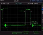
The ringing you are talking about here is this what I am seeing in my design here, just after the pulse turns off?

PWM.jpg

If in that case, how do I calculate this gate resistor? I am using an 42.2R now.

Tocotukan
 

The said "ringing" is not occuring at the gate. It's crosstalk to the measurement, created at a different switching node of the circuit. If it's related to gate resistors, then the gate resistor of different transistor.
 

So...

What do you think is the source of the oscillation/ringing I see on the gate of my MOSFET then?
 

I guess, you'll see the oscillation everywhere in your circuit. But they are neither caused by the gate driver nor having any effect on the FET, because the magnitude is low.

You should search other circuit nodes for the oscillation source.
 

Yes, oscillation everywhere. I read this thread and I was thinking that the problem explained here was an possible reason.
 

Status
Not open for further replies.

Similar threads

Part and Inventory Search

Welcome to EDABoard.com

Sponsor

Back
Top