Continue to Site

Welcome to EDAboard.com

Welcome to our site! EDAboard.com is an international Electronics Discussion Forum focused on EDA software, circuits, schematics, books, theory, papers, asic, pld, 8051, DSP, Network, RF, Analog Design, PCB, Service Manuals... and a whole lot more! To participate you need to register. Registration is free. Click here to register now.

More than 70dB isolation spdt at X band

Status
Not open for further replies.

jaehlee99

Junior Member level 1
Joined
Oct 9, 2012
Messages
19
Helped
0
Reputation
0
Reaction score
0
Trophy points
1,281
Activity points
1,401
Hello everyone..

I would like to design the SPDT which is used for Tx and Rx switching at the X band.

The isolation would be more than 70dB, would you recommend the the topolgy, such as series or shunt or series and shunt combination ?

It is also difficult to find the component at the X band frequency.

Thanks in advance
 
Last edited:

When I used to test Iridium Sat. phone LNA's/Tx chips which MOT designed in a custom MMIC chip in Phoenix, they used series shunt PIN diodes that were impedance matched and achieved > 65dB isolation up to 6GHz with very low insertion loss.
 
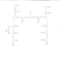
They have chips that have the SPDT series diodes, followed by shunt diodes right next to them. They will give around 40 dB isolation. then in each of the arms you need to add two additional PIN diodes, one quarter wave from the series/shunt output, and another one another quarterwave down the line.. The arms have to be in channelized housing. The bias lines leading up to the arms need lowpass filters built into them. That would give you 70 dB.

If it is narrowband enough, you could do it all just with shunt pin diodes, the first diodes being quarterwave from the T junction.


The electrical spacing diode-to-diode is 90 degrees at mid band. Because of diode parasitics, that means the microstrip lines are a little less than 90 degrees long.

VB1 would be -5 to -10 volts (reverse bias) in the insertion loss path, and 60 mA forward bias on VB2 in the isolation path.

If you starve the forward bias current, at some point you will not make the isolation. One of the benefits of using FETs in place of the PIN diodes is that you do not need much forward bias current.

- - - Updated - - -

 
biff44, thank you so much for your information.

Would you let me know how 60mA comes out for isolation path in detail ? Is that current is norminal for every PIN diode when it is forward biased?

Thanks in advance
 
Last edited:

PIN diodes, when biased on, still have some residual resistance. You want this resistance to be as low as possible to get the maximum attenuation per shunt diode. Starting at around 5 mA per diode they become useable, but with you wanting 70 dB of isolation, I would give them 15 mA each. High power switches would require even more current.

Do a quick analysis:
take a 50 ohm line and put a 5 ohm resistor to ground along the line. Analyze the insertion loss. Now make the resistor 1 ohm and repeat analysis--a big difference in dB's! Also, similarly, you have to worry about any parasitics in the PIN diode, such as series inductance to ground--too much and you do not get much isolation per diode.
 
Last edited:
Here is what I would use in place of the "T junction" If I needed a broadband switch:
**broken link removed**

- - - Updated - - -

Here is what I would use in place of the "T junction" If I needed a broadband switch:
**broken link removed**

The biasing scheme is slightly different.
 
biff44, thank again.
If I want to use another PIN diode instead of MACOm, which specification is most important for this frequency band? And one more thing, if I would like to use for high power, for example 50W, which factor is most important to select the device?
 

50 W??? then use the first schematic. You will need a diode with a wide active area and high breakdown voltage. what bandwidth?
 
Bandwidth will be 500MHz at the X band, it also need high isolation. In case of that, If I have to use the first schematic, it is difficult to find the device at the moment.
 
Last edited:

Status
Not open for further replies.

Part and Inventory Search

Welcome to EDABoard.com

Sponsor

Back
Top