BrettLaCroix
Newbie level 1
- Joined
- Apr 2, 2010
- Messages
- 1
- Helped
- 0
- Reputation
- 0
- Reaction score
- 0
- Trophy points
- 1,281
- Location
- Newport Oregon
- Activity points
- 1,301
I have a switch that uses a two button keychain remote (think car alarm/remote lock)... press one button and the relay is latched on, press the other button it is off.
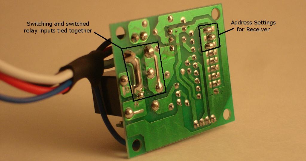
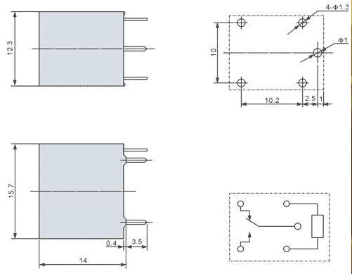
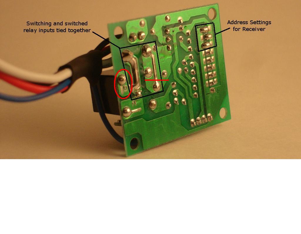
This switch uses a JZC-8FA(4181) PCB relay as the switch. My first question is this... if this relay is only used as an on/off switch... shouldn't I be able to wire in another wire so that it turns into an A/B switch? (See schematics... I am thinking that this relay has a common, a NO, and a NC... however only the NO or NC is being used right now, not both)
Secondly... this switch uses the same 12v input to power the receiver as it does to send power through the relay (switch). I want to isolate the relay power from the receiver power and simply solder in a second wire.
The power going through the relay will be coming from, and controlled by a TR-7 module and the power will only be on for 35 seconds AFTER this remote triggers the TR-7 module (trigger will be taken from pin 17 of the IC, which fires whenever a button on the remote is pressed.)
With this setup, I need the receiver to have power all the time, while only providing power through the relay for the 35 seconds.
And for those who are curious... this will be a remote open/close for my car's convertible top.
Press the "on" button on the remote, the trigger from the receiver's IC is sent to the TR-7, causing it to provide power through the relay to my convertible "top down" switch for 35 seconds.
By turning the relay into an A/B switch, I can use the "B" side to connect to the "top up" switch... thus pressing the "off" button on the remote will do the same thing... only closing the top.
So I was hoping... by looking at the photos... I can get suggestions on where to place the wire to get to the "B" side of the relay, if possible? and were to cut board to isolate the power supplies for the receiver versus the relay?
Thanks for your help!
") Brett
Brett
PS. Please Note, photos have some notations on them because they are from another person, but this board has not been modified and is how it is shipped from the manufacturer.


This switch uses a JZC-8FA(4181) PCB relay as the switch. My first question is this... if this relay is only used as an on/off switch... shouldn't I be able to wire in another wire so that it turns into an A/B switch? (See schematics... I am thinking that this relay has a common, a NO, and a NC... however only the NO or NC is being used right now, not both)
Secondly... this switch uses the same 12v input to power the receiver as it does to send power through the relay (switch). I want to isolate the relay power from the receiver power and simply solder in a second wire.
The power going through the relay will be coming from, and controlled by a TR-7 module and the power will only be on for 35 seconds AFTER this remote triggers the TR-7 module (trigger will be taken from pin 17 of the IC, which fires whenever a button on the remote is pressed.)
With this setup, I need the receiver to have power all the time, while only providing power through the relay for the 35 seconds.
And for those who are curious... this will be a remote open/close for my car's convertible top.
Press the "on" button on the remote, the trigger from the receiver's IC is sent to the TR-7, causing it to provide power through the relay to my convertible "top down" switch for 35 seconds.
By turning the relay into an A/B switch, I can use the "B" side to connect to the "top up" switch... thus pressing the "off" button on the remote will do the same thing... only closing the top.
So I was hoping... by looking at the photos... I can get suggestions on where to place the wire to get to the "B" side of the relay, if possible? and were to cut board to isolate the power supplies for the receiver versus the relay?
Thanks for your help!
BrettPS. Please Note, photos have some notations on them because they are from another person, but this board has not been modified and is how it is shipped from the manufacturer.