Continue to Site

Welcome to EDAboard.com

Welcome to our site! EDAboard.com is an international Electronics Discussion Forum focused on EDA software, circuits, schematics, books, theory, papers, asic, pld, 8051, DSP, Network, RF, Analog Design, PCB, Service Manuals... and a whole lot more! To participate you need to register. Registration is free. Click here to register now.

[SOLVED] Measuring RF power for wideband signal

Status
Not open for further replies.

raed_microwave

Advanced Member level 4
Joined
Jul 26, 2008
Messages
107
Helped
0
Reputation
0
Reaction score
0
Trophy points
1,296
Location
Kassel, Germany, Germany
Activity points
2,066
Hello

I used the power meter to measure the output IF power of low noise receiver and it was -3 dBm and later I used spectrum analyzer and the output IF power was -30 dBm with RBW of 1 MHz. The receiver has 1.2 GHz of IF bandwidh. Could you please tell me why this different in the measured power?

Regards
 

The power meter evaluates the heat generated by absorbing a wideband signal or noise spectrum. A spectrum analyzer analyzes the narrow sections of your spectrum while it can scan it over the wide band. The RBW is the width of a narrow window which scans over a wider bandwidth.
In spectrum analyzers you have three bandwidths: the first is the frequency coverage over which the narrow-band receiver is scanning. The second is the bandwidth of this narrow-band receiver. The third is the integration bandwidth of the video filter after detector.
Usually you cannot evaluate a real power of a wideband signal or noise by spectrum analyzer. You can measure a CW power and analyze signal-spectrum components by their full and relative powers. But the power meter indicates the full spectrum power.
What I'm doing is....I want to test the square-law detector whether it is working in the square or linear region.....what power level should I consider? the power level read by power meter or by spectrum analyzer? I have designed a voltage doubler circuit using HSMS-2852 diode from Avago and the datasheet said that the max. input power of diode is -20 dBm but this case is for narrow band signal. How can I evaluate power level of IF with the case of wideband noise signal ( up to 1 GHz)?
 

If you can trust your spectrum analyzer that it is calibrated to correctly read a CW signal power, you can calibrate your detector with it.
Detector response is typically square-law from TSS, ~-35 dBm, up to ~ -20 dBm, to a CW signal or a wideband one.
The problem with a wideband signal or noise in a detector is that the detector may be mismatched at some frequencies.
The best way to calibrate a detector response to a wideband signal is to use a RF power meter.

As you know......I have wideband noise signal in IF section (1 GHz). If I measure the power level of this signal by power meter, I will see the average power of whole noise bandwidth (-3 dBm) i.e. the detector is already in linear region. But if I measure the power level by spectrum analyzer, I will see just the peak power of each frequency component (-30 dBm) i.e. it is in square region.
 

I wonder if the -3dBm shown by your power sensor are (partially) caused by a DC voltage.
 

Let me try again: Given the large discrepancy between the level measured by your power sensor (wideband including DC) and the spectrum analyzer, I wonder if you have some DC voltage at the input of the power sensor?
 

The difference, 30 dB, between the power meter and spectrum analyzer readings, is due to the sensed noise bandwidth: your estimated noise bandwidth is ~1 GHz and the power of -3 dBm is read on the power meter; On spectrum analyzer, the window is ~1 MHz wide, so it reads -30 dBm.
The correct power to the detector is -3 dBm which is too much for a square-law detector.
At -20 dBm, a good detector can have K ~ 2500 mV/mW, therefore ~25 mV detected voltage. Over that, a square-law detector usually behaves "linearly" but some fine detectors can be damaged with -3 dBm!
 

There is no discrepancy because the power meter measures the average power for the whole noise bandwidth and the spectrum analyzer measures the peak of power for each frequency component depending on the RBW. At the input of detector there is wideband noise signal and I want to extract the DC component from this signal by using Square-law detector. My problem is that the datasheet of diode (HSMS-2850) said the max. input power is -20 dBm for square region. At the same time I measured the voltage sensitivity of detector and I found it is still working in square region with -3 dBm of input power. The discrepancy is between my measured results and the information in datasheet :(
 

The difference, 30 dB, between the power meter and spectrum analyzer readings, is due to the sensed noise bandwidth: your estimated noise bandwidth is ~1 GHz and the power of -3 dBm is read on the power meter; On spectrum analyzer, the window is ~1 MHz wide, so it reads -30 dBm.
The correct power to the detector is -3 dBm which is too much for a square-law detector.
At -20 dBm, a good detector can have K ~ 2500 mV/mW, therefore ~25 mV detected voltage. Over that, a square-law detector usually behaves "linearly" but some fine detectors can be damaged with -3 dBm!

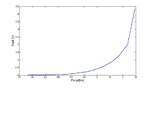
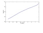
As I told you that I have designed voltage doubler (two of Diodes). I have measured the voltage sensitivity of detector and it is about 3 mV/uW....I have seen it is still working in square region !!!! I have used the output signal of LNB as wideband noise signal and amplify more the IF signal by 20 dB of gain and later I was attenuating this signal manually and I have measured the output voltage of detector by voltmeter.
Sqaure.jpgSqaure1.jpg
 

noise bandwidth is ~1 GHz and the power of -3 dBm is read on the power meter

Thermal noise is -174dBm/Hz, or -84dBm at 1GHz bandwidth. If the -3dBm is only from wideband noise, the noise would be 81dB above thermal noise. Isn't that a little bit too much?

edit: I might have misunderstood the question. Did you say that your input test signal is a wideband noise source indeed?
 
Last edited:

Thermal noise is -174dBm/Hz, or -84dBm at 1GHz bandwidth. If the -3dBm is only from wideband noise, the noise would be 81dB above thermal noise. Isn't that a little bit too much?

edit: I might have misunderstood the question. Did you say that your input test signal is a wideband noise source indeed?

In my post, I said the power level not the noise level....the noise level is about -95 dBm/Hz and the power level is -3 dBm for 1 GHz bandwidth.
I used the output signal of LNB as wideband noise source for testing the detector
 

To relate the spectrum analyzer to the power meter measurement, we need to know the selected SA detector characteristic. Recent spectrum analyzers have power averaging and channel power measurement capabilities, that achieve results near to a power meter. The difference between measurements of about 2 dB isn't really large, however.

Both measurements suggest operation of the diode detector outside square law range. Also the slope in your measurement isn't true square law rather than transition mode, as far as I see. If I understand right, the -20 dBm square law limit is for CW signals. It should be lower for noise due to the crest factor.

Another question, that has been already addressed by jiripolivka is, if you actually achieve broadband matching and respective frequency independent power measurement in your detector circuit. To verify the frequency response, you would preferably use a signal generator.

Thank you so much for your information............really I'm always confuse between square region and linear region :(
 

Status
Not open for further replies.

Part and Inventory Search

Welcome to EDABoard.com

Sponsor

Back
Top