Continue to Site

Welcome to EDAboard.com

Welcome to our site! EDAboard.com is an international Electronics Discussion Forum focused on EDA software, circuits, schematics, books, theory, papers, asic, pld, 8051, DSP, Network, RF, Analog Design, PCB, Service Manuals... and a whole lot more! To participate you need to register. Registration is free. Click here to register now.

Signal level threshold amplifier for HF RF

neazoi

Advanced Member level 6
Joined
Jan 5, 2008
Messages
4,122
Helped
13
Reputation
26
Reaction score
15
Trophy points
1,318
Location
Greece
Activity points
36,951
Hello,
I am trying to achieve the next:

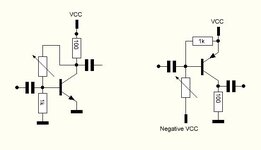
Having an HF amplifier that can amplify incoming antenna signals, ONLY higher than a preset signal level. All signals below that preset level should be ignored.
I have achieved this behaviour with a class-C amplifier but this one works only on very high threshold of input signals, above 0.5V or so.
What I need, is a similar behaviour with the class-C amplifier but for much lower signal levels (those encountered on an antenna).
 
I presume a non-linear amplifier, e.g. class-C, is useless for antenna signals if you have more than one signal "on air". Non-linear amplifiers are only applicable after selecting a single signal from incoming RF, e.g. in IF amplifier.
 

    neazoi

    Points: 2
    Helpful Answer Positive Rating
I presume a non-linear amplifier, e.g. class-C, is useless for antenna signals if you have more than one signal "on air". Non-linear amplifiers are only applicable after slecting a single signal from incoming RF, e.g. in IF amplifier.
Thank you, I understand what you mention. This is a special case I do not care that much about the distortion, IMD. What I care the most is about achieving that low threshold, or "knee" where amplification will cease.
 
Applying gradually DC bias to the Class-C amplifier (which will increase the quiescent current), you can decrease the threshold of the input signal at a value that you want.
Increasing the quiescent current, the amplifier will move gradually from Class-C to Class-AB.
 

    neazoi

    Points: 2
    Helpful Answer Positive Rating
Applying gradually DC bias to the Class-C amplifier (which will increase the quiescent current), you can decrease the threshold of the input signal at a value that you want.
Increasing the quiescent current, the amplifier will move gradually from Class-C to Class-AB.
That's interesting! Of course, going more and more towards class-A should reduce the threshold.
That might sound trivial, but is it enough to use a variable resistor connected like this, to the bases of these complementary amplifiers, so as to achieve that?
I will try to simulate that, but I need a guidance towards the correct way.
If this could be done without a negative voltage that would be ideal.
 

Attachments

  • Capture.JPG
    Capture.JPG
    15.9 KB · Views: 50
It will work but if you are thinking about microvolt level signals the bias will have to be exceptionally stable and the temperature kept stable, the signal will be tiny compared to the voltage needed to provide partial bias. Also remember that class C is not linear, you will introduce distortion which in a small signal scenario will mean intermodulation and spurious carrier mixing problems which implies strong filtering before the input as FvM stated earlier.

I think I know what you are trying to achieve but I doubt you will get the results you want. I think you are trying to pull the stronger signal out of a noisy background by setting a threshold it has to exceed to be audible. A kind of squelch but at antenna level voltages. Consider that the filtering you would need to isolate the wanted signal probably does 99% of what you want.

Brian.
 

    neazoi

    Points: 2
    Helpful Answer Positive Rating
It will work but if you are thinking about microvolt level signals the bias will have to be exceptionally stable and the temperature kept stable, the signal will be tiny compared to the voltage needed to provide partial bias. Also remember that class C is not linear, you will introduce distortion which in a small signal scenario will mean intermodulation and spurious carrier mixing problems which implies strong filtering before the input as FvM stated earlier.

I think I know what you are trying to achieve but I doubt you will get the results you want. I think you are trying to pull the stronger signal out of a noisy background by setting a threshold it has to exceed to be audible. A kind of squelch but at antenna level voltages. Consider that the filtering you would need to isolate the wanted signal probably does 99% of what you want.

Brian.
Hm... I see. If the bias is that critical in the signal amplification then this would be a problem. You see, class AB amplifiers have bias to avoid intermodulation distortion, but I want to do a different thing. That is have a class C amplifier biased to behave more like a B one. Or the other way around, have a class B amplifier biased to behave more like a C one. Actually it is this C to B transformation that I would like to achieve and one way to do this would be biasing, although I do not know how to do it on the PNP circuit (I am more familiar with NPN circuits).
As I understand it, light biasing will remove this 0.6v of threshold, as the amplifier goes from class C to B, perhaps even reaching the AB region.
 
Class A is where the amplifier conducts all the time, or at least all the time except at peak negative signal excursion.
Class B only conducts at most over 50% of the signal cycle.
Class C conducts over less than 50% of the signal cycle.

What you are seeking is Class C to avoid the lowest signal levels but then immediately changing to Class A as the signal gets stronger. I don't think you will achieve that, even passing into Class B region implies rectification of the signal.

If I had to do what you propose, I think I would use a conventional superhet front end to produce a convenient fixed IF, filter it using steep sided filters to eliminate adjacent channel signals then split it two ways. One way would be through an IF amplifier with voltage controlled gain, the other way through a rectifier, filter with a short time constant and a DC amplifier to recover the signal envelope. Then use the recovered envelope to control the gain of the other chain. A kind of positive AGC to which you can set thresholds and amounts. I think using two signal paths like that would be essential, if you tried positive AGC by simply using conventional AGC but reversing the polarity you would risk turning the IF stages into an oscillator at AGC time contstant rate.

Brian.
 

    neazoi

    Points: 2
    Helpful Answer Positive Rating
You need a RSSI circuit. It's available in Integrated Forms in Analog Devices.
You define a level ( preset value) then you power on/power off the signal chain afterwards. It just needs a good calibration.
Similar mechanism is used in old type Walkie-Talkie radios as squelch. AGC Circuit can also be used instead.
 
I think the objective is to pull the strongest of mixed signals above the level of the weaker ones by applying additional gain if the level is higher than some threshold. Being honest, although it sounds feasible, I can't see how it can work effectively because the additional gain would also amplify the weaker unwanted signals at the same time. You would get an "all or nothing" situation where it was quiet until anything strong enough arrived then all the signals become loud at once.

Ignoring signals below a threshold level then passing them through a gate is normal squelch regardless of mode. If a comparator is used to gate only stronger RF cycles it destroys anything AM but would work with FM.

There may be a completely alternative method worth trying, and I'm assuming the majority of HF signals Neazoi are AM, that is to use synchronous demodulation and apply a notch filter to the recovered audio. It would give slightly better S/N ratio and allow rejection of the beat tone between stations on slightly different frequencies. Done at IF where the frequency is fixed isn't too difficult, a PLL locks to the incoming carrier and its VCO operates the detector. I have it on a receiver here (an aging but rather good HF-225) and can confirm it works well but only has a lock in range of about 200Hz so tuning has to be precise.

Brian.
 

LaTeX Commands Quick-Menu:

Part and Inventory Search

Welcome to EDABoard.com

Sponsor

Back
Top