Continue to Site

Welcome to EDAboard.com

Welcome to our site! EDAboard.com is an international Electronics Discussion Forum focused on EDA software, circuits, schematics, books, theory, papers, asic, pld, 8051, DSP, Network, RF, Analog Design, PCB, Service Manuals... and a whole lot more! To participate you need to register. Registration is free. Click here to register now.

Measuring Power out of a 3-Phase Motor controller/inverter

Status
Not open for further replies.

brucelee2

Member level 2
Joined
Aug 22, 2009
Messages
49
Helped
6
Reputation
12
Reaction score
3
Trophy points
1,288
Location
on a PCB
Activity points
1,638
Hi All,

Im working on project for my final bachelor thesis that involves an EV test bench setup.
DC battery bank(180V)>>Motor-controller>>3-phase delta connected motor.

I need to measure the power at different stages. Does anyone have an idea for measuring the power coming out of the controller/inverter? The problem is the signal patterns leaving the controller, discrete voltage switching. The test setup will be used with labview and data acquired with NI field points.

I know there are 3-Phase power measuring devices out there but not sure how they will behave when exposed to the signal coming out of the inverter/controller.

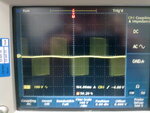
Ive attached an image of a scope when probing across 2 phases. Any ideas how to measure the power at this stage?

THanks for the help!;-)

Bruce
 

Attachments

  • 28022011084.jpg
    28022011084.jpg
    401.4 KB · Views: 113

I might be wrong but, maybe those ACS current sensors from Allegro micro might do it.
They have 80 Khz bandwidth and they are available from 5 upto 200 Ampere's.
(do place an rc filter after the ACS to equalize the reading)

Goodluck.
 
Last edited:

The motor current will have nearly sine waveform and contain only a small switching frequent component. A hall effect current transducer has the advantage, that it can acquire low frequent currents down to DC without a cut-off frequency. An Allegro current sensor would be O.K. if you don't have very high accuracy requirements.
 

Hi Fvm and walkura

I realise the current will be of sine form as the motor windings act as a kind of filter. I fully understand how to measure the current, im using LEM modules. Its the calculation of power that im not 100% sure of. I can filter the voltage over the phases(removing the high frequency harmonics) but this will imply a filter. Filters cause lag, attenuation...ect...depending on the frequency; the frequency of these signals are motor speed dependent. There will be an incorrect phase shift associated with the signals due to the filter.

Is there an easy way to measure the 3-phase power with some device, bearing in mind the voltage signal form over the phase.

Thanks for the replies

Bruce
 

For a correct power measurement, you have to average the product of instantaneous current and voltage. If using filters, they have to apply the same phase shift to voltage and current. You should be clear however, if you want to include the switching frequent power component with your measurement. They won't be large, according to the current waveform, but a certain amount can be expected. Otherwise you can filter the PWM frequent components, observing the said phase requirement.
 

Unfortuantely, the manual doesn't tell about the instruments capability to deal with PWM voltages. There's a certain risk to get incorrect measurements. You should ask the manufacturer or an authorized representative/distributor if the instrument can measure the output power of a VFD inverter.
 
Ill give the company a call in asia to find out...I assume if the device samples at a fast enough rate to get a good average then things should be ok.
 

I assume if the device samples at a fast enough rate to get a good average then things should be ok.
I agree. Also effective low-pass filtering would be O.K. as long as the current has almost a sine waveform.
 

I think NI-Field point is over load and not require for this test, please try with PCI-6221 or 6229 Card which have higher sample rate and easy to handle using normal windows(R) Machine.
 

Hi All,

An update.. We have decided to use a different approach. Instead of using power measurment devices with a clamp(risk of inaccurate measurment is to high) or field point modules(too slow anyway) we have decided to use a combination of high voltage instrumentation amplifiers and true RMS IC's. The three phase current from one phase is read using an LEM module and the voltage over the phase using a instrumentation amplifier. Both signals are used by a RMS IC and then the result of each multiplied. This is then done for the other phase aswell.
 

Status
Not open for further replies.

Similar threads

Part and Inventory Search

Welcome to EDABoard.com

Sponsor

Back
Top