Continue to Site

Welcome to EDAboard.com

Welcome to our site! EDAboard.com is an international Electronics Discussion Forum focused on EDA software, circuits, schematics, books, theory, papers, asic, pld, 8051, DSP, Network, RF, Analog Design, PCB, Service Manuals... and a whole lot more! To participate you need to register. Registration is free. Click here to register now.

measurement of AC line voltages using PIC16F877A

Status
Not open for further replies.

Qaisar Azeemi

Full Member level 5
Joined
Feb 11, 2011
Messages
315
Helped
16
Reputation
32
Reaction score
15
Trophy points
1,298
Location
Peshawar, Pakistan, Pakistan
Activity points
3,829
Hi friends!
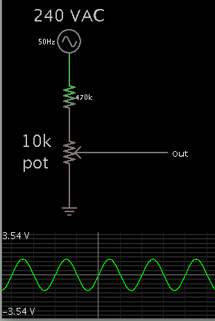
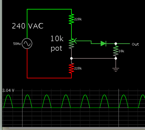
I want to measure the AC line voltages 220V using pin RA5 of Pic16F877A, and display it on LCD Screen. kindly help me with circuit diagram and code. i also studied the mikrochip application note AN521 bu't cant get any specifice solution. they just add a 5M ohm resistor in series with RA0. kindly tell me how should i get the voltage sample form 220V AC line feed it into the ADC of PIC and display the correct value on LCD screen. i need circuit diagram of voltage sample circuit and a little code for that.

any help will be much appreciated.

thanking you all in anticipation.
 

The 5M resistor is one way to attenuate the high VAC. It assumes your device has internal impedance which provides a complete path for the incoming house current.

It may or may not result in a volt level readable by your device.

To adjust the 240 VAC down to a readable range, it is more convenient to use a potentiometer.

Schematic:

8250637000_1348906374.png


The high resistance in series is needed to limit current 'just in case'. A value of 470k keeps it under 1mA.

This will produce AC. If you only want DC to reach your device, put a diode on the output.

If you want to smooth out the waveform, add a capacitor and resistor.

- - - Updated - - -

It is best to put a high resistance in each connection to mains AC.

I added a diode, in case your device should only have positive polarity applied to the input.

8979381700_1348908382.png
 

i tried your circuit with a 100uf capacitor parallel to 10k resistor but unfortunately it didn't work... the LCD displays constantly and swiftly changing values form -128 to +127 but didn't display the true and fix value. here is my code:

Code:
void main()
{

 // CONFIGURING SFRs:
  cnt=0;
  TMR0=0;   // loading vlaue of timer0 interrupt
  OPTION_REG=0x87;  // for timer 0; presscaller 1; 256
  ADCON1=0x07;   // adc reg initialization  ; changes port a to digital I/O
  INTCON=0xA0;  // for timer0  ; interrupt reg initilization

  // OUTPUTS:
  TRISB.f2 = 0;       //led out put
  TRISE.F2=0;        // gen cont output
  TRISC=0x00;        // portC output For LCD
  PORTC=0X00;        // initilization port c
  TRISB.f0 = 0;       //led out put
  
  // INPUTS:
  TRISB.f7 = 1;   //temp
  TRISB.f6 = 1;   // oil
  TRISD.F0=1;    // ENTER
  TRISD.F1=1;    // RESET
  TRISD.F2=1;    // UP
  TRISD.F3=1;    // DOWN   */
  TRISA = 0xFF;     // port A as input
  TRISD = 0x0F;     // Lower nibble of port D as input

  T1CON.TMR1ON=1;
    PIR1.TMR1IF=0;
    TMR1L=0X00;
    TMR1H=0X00;
      ADC_Init();
    if(mains==P)    // if main is Present.
    {
       lcd_init();
       start();

    }
   
    start:
  lcd_init();
  Delay_ms(500);

while(1)
  {

  if(mains==A)    // if main is absent.
    {
     Lcd_Cmd(_LCD_CLEAR);
     Lcd_Out(1,1,CopyConst2Ram(msg,mna));    //mains not available
     Delay_ms(4000); // wait for 4 seconds to ensure power failure
     if(mains==P)     //check again
     continue;

     //Delay_ms(1000);
     Lcd_Cmd(_LCD_CLEAR);                    // Clear display
     //Delay_ms(600);
     Lcd_Cmd(_LCD_CURSOR_OFF);
     Lcd_Out(1,1,CopyConst2Ram(msg,mna));    //mains not available
     Lcd_Out(2,1,CopyConst2Ram(msg,sg));     //starting genset
     Delay_ms(1000);
     gen();

    }
    else           // if main is present .........
    {

      Lcd_Cmd(_LCD_CLEAR);                    // Clear display
      Lcd_Cmd(_LCD_CURSOR_OFF);
      Lcd_Out(1,1,CopyConst2Ram(msg,mok));   // Write text in first row
      Lcd_Out(2,1,CopyConst2Ram(msg,mol));    // mains overload
      Delay_ms(2000);
        //gen_cont=0;   //Turn off generator contactor
       //main_cont=1;   //Turn on main contactor
      Lcd_Cmd(_LCD_CLEAR);                    // Clear display
      Lcd_Out(1,3,CopyConst2Ram(msg,st));   // Write text in first row
      Lcd_Out(2,4,CopyConst2Ram(msg,pl));     // pvt ltd
      Delay_ms(1000);
    }


              for(i=0; i<96; i++)
              {
                       Lcd_Cmd(_LCD_SHIFT_RIGHT);
                       Delay_ms(t);
                        if (enter==0)
                         i=96;

                        if ((enter==1) && (reset==0) && (up==1) && (down==1))   //press reset to exit
                        {
                           Delay_ms(ms); // wait for switch debounce
                           i=0;
                           goto start
                        }
                        
                        if(mains==A)
                        {
                          i=96;
                        }
              }


   }    // while

}      // main

Code:
gen()
{

   
                         if(frq==1)   //on timer 1 interrupt
                         {
                             k++;

                                if(k==155)    // after 16 interrupts = 1sec
                                  {
                                     // l2=~l2;
                                      shortToStr(G,op);
                                      Lcd_Out(2,2,op);
                                      Lcd_Out_CP("Hz");
                                      Delay_ms(200);
                                      G=0;
                                      k=0;
                                   }
                             T1CON.TMR1ON=1;
                             frq=0;
                             
                         }

 if (oil !=0 || tmp!=0)
                   {
                        
                          ADCON1 =0x00;
                       
                          tmp = ADC_Read(4);
                          Delay_ms(ms);
                          shortToStr(tmp,op);
                          Lcd_Out(2,10,op);
                          Lcd_Out_CP("V");
                          Delay_ms(ms);
                          ADCON1 = 0x07;
                       
                    }
}

i am using the pins RA0, RA1 and RA2 as digital i/os and RA3 and RA4 as analog IOs...
my above code may seems to be unorganized/incomplete but it is the part of full 1000+ lines code, just i paste small related codes here. i have to detect the input toggling on pins ra0, ra1 and have to detect the frequency of incoming signal at ra2 the ac voltages at ra4. i am using ra3 for the other purpose as an analog input.

please detect where i am going wrong...
 

This project is risky because you are allowing mains power to contact your device which is meant for low voltage.

Did you test that a low DC voltage can be read across the 100 uF capacitor? Does your meter show any AC component?

Did you test your pic with a stable DC voltage, to make sure it can convert analog volt levels?

Your project has several parts to it. Right now you must test each part, and make certain each is doing a reliable job. Later you can combine the separate sections.

Sorry, I am not familiar with pic programming, so I am of little help with your code.
 

You can simply use full wave precision rectifier circuit and then give it to controller pin through a RC filter circuit. Add a preset and then adjust your ADC as 5v corresponds to max. voltage you want to read. Then calibrate via that preset.
 

This project is risky because you are allowing mains power to contact your device which is meant for low voltage.

Did you test that a low DC voltage can be read across the 100 uF capacitor? Does your meter show any AC component?

Did you test your pic with a stable DC voltage, to make sure it can convert analog volt levels?

Your project has several parts to it. Right now you must test each part, and make certain each is doing a reliable job. Later you can combine the separate sections.

Sorry, I am not familiar with pic programming, so I am of little help with your code.

thank you for your kind reply Brad... answers to your inquiry are:
1)Did you test that a low DC voltage can be read across the 100 uF capacitor?
===> Yes i test the voltages.
2) Does your meter show any AC component?
===> No it is showing DC component. and i have DVM.
3)Did you test your pic with a stable DC voltage, to make sure it can convert analog volt levels?
====> yes it is converting smooth dc to analog signal and i have successfully displayed it on my LCD screen. but i dont know why is it not displaying ac values even i have converted it to dc and reduced its amplitude to less than 2.5V????? :?: i don't know weather the problem is in hardware design or in my code?
 

the LCD displays constantly and swiftly changing values form -128 to +127 but didn't display the true and fix value.

In binary these values are 11111111 and 01111111. (Zero is in the middle.)

I believe your display shows the least significant byte. It suggests that your values are really much larger. Is the variable dimensioned to occupy one or two or four bytes?

Then there is the issue that the value is changing rapidly. It should be DC.

So it seems that AC must be getting into the circuitry somehow. Perhaps it is because mains AC is connected. Even if you connected a high resistance at each incoming wire, there is still a chance the high voltage has enough effect to create unstable readings.

You may end up needing to use a step-down transformer.

you mean voltage values must be too small to apply to the micro? i applied less then one volt to micro.... should it be in milivolts? here situation is that if i turn the resistor to provide 0V to the micro's pin i.e; ground it... still it shows variable values... however diode is connected and capacitor is also connected to make it smooth dc, and i think there should be no chance to arrive high variable pulses to drag the values of ADC to extremes..... i think there may be some coding problem.. or should i increase the value of the capacitor????
 

you mean voltage values must be too small to apply to the micro? i applied less then one volt to micro.... should it be in milivolts?

It needs to be within the specified range for your pic.

The issue I mentioned in post #7 is based on the resolution of your ADC. Suppose it is 12 bits. What will happen if you store its result in a variable that holds 8 bits? Will it generate an error? Will it overwrite neighboring memory, changing the value of another variable?

I have no experience with microcontrollers. I cannot be sure this is the problem. The repeated -128 and +127 is a pattern which looks like a clue to an overflow, or an error message of some kind.

here situation is that if i turn the resistor to provide 0V to the micro's pin i.e; ground it... still it shows variable values...

This does not sound good. It's time to test the ADC again with a range of DC volt levels.

Do not have it connected to mains AC while you do the tests.
 

Hi, I know it's a little late but is important for other peoples who read this to understand what is happening with the "non stable" reading from ADC of an AC :

- circuits posted here are voltage divider and at the output is a scaled voltage which can be measured by an ADC.
- the current is AC and not DC
- using a diode on output will result in exposing the analog pin only to the positive sine wave
- when this signal is simply read, it will be only an instant voltage and will be displayed oscillating between min (0) and max ( input*2^resolution) (the -128 .. +127 is a consequence of unsigned/signed variable type)
- for RMS Voltage, the instant voltage need to be integrated over the period of positive sine wave, for AC voltage need to be retained the max value read over the positive sine wave. For 220V 60Hz, the positive sine wave has a period of 1s / 60Hz / 2(pos/neg) ~= 8.33 ms (120Hz). for a high accuracy of reading of the highest AC value, the ADC reading need to be triggered with a minimum 10 times frequency (1200Hz - 0.833ms) a higher freq is a higher accuracy. Also with this method can be approximate the zero-cross event
 

hello,

if you use a 100µF accross the 10K resistor, you will get the peak value , nearly constant ..because analog input current is very low.
But in fact, i think you get variing value because your ground (0V) must be affected by loosing current from AC power supply and other components
( inputs, other analog..)

Is your 0V (PIC power supply) connected to the earth ?

I think it's better to use a litle trafo (230V/9V or less any VA) to get galvanic insulation.
and scale it by a resistor network to get 0 to near 5V on ADC input.
so you will get 0 to 1023 point for the peak to peak AC value

you can lauch a sequence of 32 readings :
sample ADC every 0.325 mS and store 32 samples to get one complet sinusoide
32*0.625=20mS
search minima and maxima value, and you have peak to peak voltage.
 

h i..... i made a ac voltmeterr by converting ac through transformer to 12v ac , then rectifying and adding a cap across it ....used pot to adjust the voltage to 5v accordingly....but my reading is not stable ...its having ac component as well.........

what should i do ...if i place big capc across it the signal changes slowly and becomes unusable for stabilizer.........design....

Please suggest what to do.......to sense accurate ac voltage by converting to corresponing dc without ac component or any delay in reading....
 

Status
Not open for further replies.

Similar threads

Part and Inventory Search

Welcome to EDABoard.com

Sponsor

Back
Top