Continue to Site

Welcome to EDAboard.com

Welcome to our site! EDAboard.com is an international Electronics Discussion Forum focused on EDA software, circuits, schematics, books, theory, papers, asic, pld, 8051, DSP, Network, RF, Analog Design, PCB, Service Manuals... and a whole lot more! To participate you need to register. Registration is free. Click here to register now.

Measure very low valued photoresistor

Status
Not open for further replies.

Darkcom

Newbie level 3
Joined
Aug 16, 2016
Messages
3
Helped
0
Reputation
0
Reaction score
0
Trophy points
1
Activity points
29
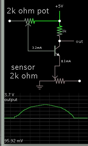
I am measuring the very low valued resistance of photoresistor, and I found this circuit. Could anyone explain for me, and what is the op amp for this circuit? Thanks alot! Capture.PNG
 

The circuit does not work for a photo resistor, only for photo elements that generate a current on it's own.

The circuit can be modified by connecting R1 to a reference voltage, making a voltage divider with the photo resistor. What's the expected resistance range?
 
The opamp is an amplifier that amplifies the voltage produced by the photocell. A photocell is not a photoresistor but some dictionaries wrongly say they are both the same. A photoresistor is a cadmium-sulfide type.

A diode (1N4148) in a see-through case or an LED is a tiny photocell. Just now I tried them and they produce a small DC voltage that I measured with my multimeter.

The circuit you show might use an old LM324 quad or LM358 dual opamp that have positive input bias current that can produce a high voltage across R1 when the photoresistor is a high resistance when dark and a low voltage when in the light.
 

The circuit does not work for a photo resistor, only for photo elements that generate a current on it's own.

The circuit can be modified by connecting R1 to a reference voltage, making a voltage divider with the photo resistor. What's the expected resistance range?

Hi, thanks for replying me. I put the photocell under the direct sunlight, thus the resistance is around 38Ohm. Then I rotate the photocell, to measure the relation between the resistance and incident light angle. Since the light illuminance of direct sun is too high (128000 lux), thus the value changes very small. I have tried the voltage divider, but it seems not sensitive enough. The expect range is 38 -2000 Ohm. Sorry for disturbing you! Having a good day.
 

Hi,

Please tell what exactely is your photosensiteve device? (Manufacturer and exact type).

A photocell will produce current. It has no dedicated "resistance" like a photoresistor.

Measuring the resistance of a photocell with an ohm meter gives no meaningful value.

Klaus
 

Hi, the device I used is photoresistor VT90N2. Now I understand the circuit I posted cannot be used. I am trying to measure the resistance by the Arduino UNO by a voltage divider circuit. But the change in resistance is quite low compare to arduino resolution..
 

Hi,

You need the correct setup.

if you expect a range of 38..2000Ohm, then I recommend a fixed resistor (as divider) with value: sqrt(38 * 2000) = about 275 Ohms.

If you connect it to a 5V source than the ADC sees
0.607V @ 38 Ohms
4.395V (= 5V - 0.605V) @ 2000 Ohms.

So with both extremes you are about 600mV from the rails.
With a 10 bit ADC this gives a resolution better than 1% at both extremes.

Klaus
 

The resistance change of a photoresistor is nonlinear with change in light level so you need to determine the resistance change over the light level variation you will experience and then design the measuring circuit accordingly.
 

A photocell will produce current. It has no dedicated "resistance" like a photoresistor.

Measuring the resistance of a photocell with an ohm meter gives no meaningful value.
Excelitas Technologies Corp, formerly PerkinElmer Optoelectronics, formerly Heimann GmbH, is labeling LDR photo resistors "photo cells" since ever.
 

The resistance change of a photoresistor is nonlinear with change in light level so you need to determine the resistance change over the light level variation you will experience and then design the measuring circuit accordingly.

That smells like work. Any suggestion in how to get that variation "coeficient" in a simple way?
 

For a photoresistor you need to force a current (or voltage) and
measure the voltage (or current). A photovoltaic device can and
will provide its own bias from illumination. An alternative setup
with the same op amp might be to put a reference voltage on
IN+, and put the photoresistor from IN- to GND with a feedback
fixed resistor. Then simple math on the output voltage w/ the
input reference value can give you Rphoto.
 

That smells like work. Any suggestion in how to get that variation "coeficient" in a simple way?

Have a look at this method of amplifying. It's a transistor in common-base operation. It has a low input impedance (as compared to common-emitter or common-collector). The photoresistor is in the emitter leg, in the path of bias current. As its resistance changes, it changes the bias. High gain is possible.

6199080200_1471430324.png


The bottom potentiometer stands in for the photoresistor. It was moved from left to right, then back again. If you adjust values right, you may get the response you want at bright illumination.
 
Status
Not open for further replies.

Similar threads

Part and Inventory Search

Welcome to EDABoard.com

Sponsor

Back
Top