Continue to Site

Welcome to EDAboard.com

Welcome to our site! EDAboard.com is an international Electronics Discussion Forum focused on EDA software, circuits, schematics, books, theory, papers, asic, pld, 8051, DSP, Network, RF, Analog Design, PCB, Service Manuals... and a whole lot more! To participate you need to register. Registration is free. Click here to register now.

MCLR pin in PIC....Problem

Status
Not open for further replies.

JAMAL JIMI

Member level 1
Joined
Dec 14, 2013
Messages
40
Helped
0
Reputation
0
Reaction score
0
Trophy points
6
Activity points
233
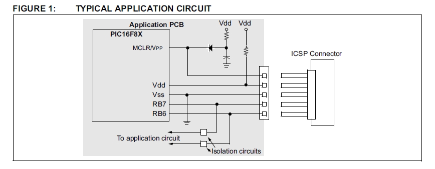
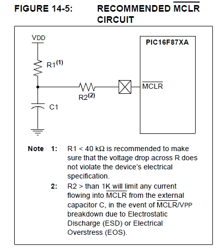
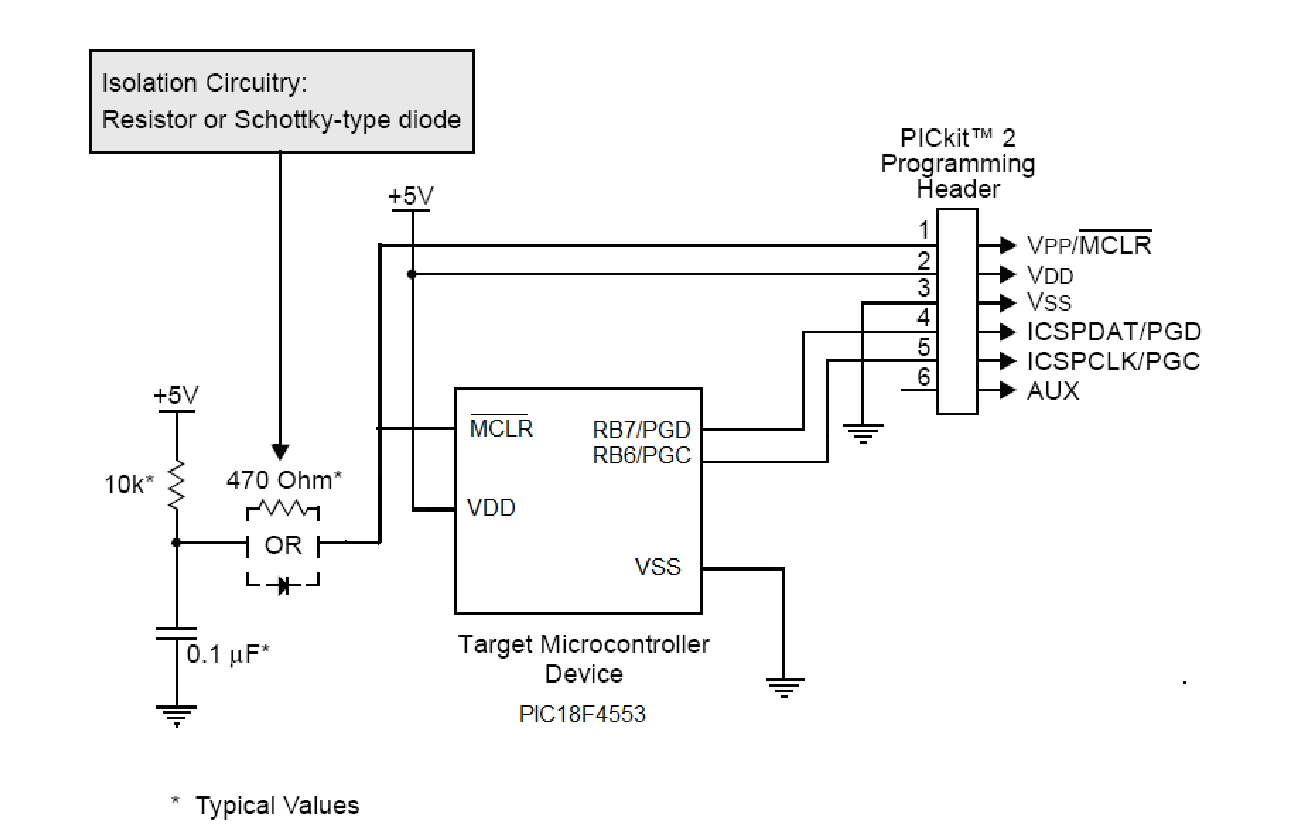
I have connected the MCLR pin of PIC 16f876 with a capcitor and resistor as shown in the datasheet but there is a problem.............please tell me the capacitor and resistor ratings which i should use??
 

Typically, a 10K ohm resistor is employed for a pullup resistor, the capacitor is typically in the100nF range, however I always employ a Schottky diode for isolation as in the first image rather than a resistor R2 for isolation in second image.

Also, don't forget the bypass/decoupling capacitor (100nF) close to the pins between VDD and VSS.


BigDog
 
u can refer following link for your doubt
https://www.edaboard.com/threads/297144/

- - - Updated - - -

i also found a circuit which used for reset
here is schematic
MCLR+Reset+Circuit.png

but i am also confuse that which one is better from those two.
 
The diode method is safest but it depends upon the way you program the device. If you program it out of circuit you can use the simple R and C method, if you use in-circuit programming you have to block the programming voltage from feeding the other components at the MCLR pin. That is why a diode is a good idea but the lower 10K resistor in post #13 MAY be enough to block the high voltage.

Brian.
 

yes but which one you will recommand for projects works in robust environment
 

All will work equally well. The issue is to do with how you program the PIC and if it is likely you will ever need to re-program it in the future. If you can remove the PIC and program it in other equipment there is no issue and you can use the simple RC circuit. If it has to be programmed in-circuit (while mounted on the board with other components connected to it) you have to ensure that the voltages needed to perform the programming operation will not damage or be loaded too much by the other components. For example, the MCLR will work in most cases if it is connected directly to VDD but if you then tried to put 12V on it to start the programming process it would try to lift the whole VDD supply to 12V and might cause damage elsewhere. The components are there to allow normal VDD to reach the pin so it can reset properly but prevent a higher voltage feeding back to other parts of the circuit.

Brian.
 

The question about whether to use a capacitor on MCLR continually comes up, and the answer seems to be dependent, at least in part, on the actual programmer that is being used. For example, the user manual for the PK3 directly contradicts advice given here and by MIcrochip in other publications and in its component datasheets.

Capture.PNG

Albeit, the PK3 seems to have a puny power supply, which might explain MIcrochip's advice. Overall, though, if one surveys datasheets for various chips you will find an ambivalence on whether the capacitor must be included, is optional, or should not be included. A score card by the manufacturer might help.

As to the OP's question, what programmer is being used? What does the user manual for that programmer say?

John
 

I would only suggest a diode on the MCLR pin and only in the supply from VDD. Adding one in the PGC or PGD pins would be asking for trouble, especially in series with the programming signals.

Brian.
 

Status
Not open for further replies.

Similar threads

Part and Inventory Search

Welcome to EDABoard.com

Sponsor

Back
Top