Continue to Site

Welcome to EDAboard.com

Welcome to our site! EDAboard.com is an international Electronics Discussion Forum focused on EDA software, circuits, schematics, books, theory, papers, asic, pld, 8051, DSP, Network, RF, Analog Design, PCB, Service Manuals... and a whole lot more! To participate you need to register. Registration is free. Click here to register now.

MCLR as digital input is resetting the device

Status
Not open for further replies.

HighTechPower

Member level 5
Joined
Jul 10, 2020
Messages
82
Helped
0
Reputation
0
Reaction score
0
Trophy points
6
Activity points
639
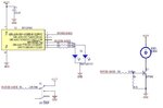
Hi. I'm using PIC12F683 in a circuit. I'm using it's pin 4, MCLR as digital input by adjusting the configuration bits accordingly. I have connected a SPDT switch to pin 4 whose level can be either 3.3 V or 0 V, however whenever there is a change in input voltage level at pin 4 (low to high or high to low) by changing switch position, it resets pin 7 (perhaps the whole device). Any idea why this is happening and how to avoid that.
 

Hi,
Show your code and setup.
Otherwise we can just guess.

Klaus
 

Attachments

  • 12F683.jpg
    12F683.jpg
    59.1 KB · Views: 81

Read previous reply.

Provide the settings witch are being programmed into device.
Or, show the code, if these configurations are there as pre-proprocessor directives.
 

Hi,
Show your code and setup.
Otherwise we can just guess.

Klaus

Please attached here find the full schematic and code as well.

Code:
#include <xc.h>

#define _XTAL_FREQ 4000000

void init_micro (void);
void init_timer (void);
void init_adc (void);
void init_pwm (void);
void read_adc(void);
void pwm_dr (unsigned int dr);
void status (void);
int abval (int);

static int dr = 0, counter_a = 0, counter_b = 0, counter_c = 0, counter_d = 0, adc = 0, flag_c = 0, buzzer_flag = 0;
//static signed long sample_fresh = 0, sample_previous = 0, filtered_previous = 0, filtered_fresh = 0, temp_sample = 0, temp_filtered = 0;

#define SBIT_LED_CHARGING GP4
#define SBIT_LED_CHARGED GP5
#define SBIT_BUZZER GP2
#define TRUE 1
#define FALSE 1
//#define PB_SWITCH GP0
#define PB_SWITCH GP3
#define POWER_GOOD GP0

void main (void)
{
    init_micro();
    init_adc();
    init_timer();
//    init_pwm();
    do
    {
    }
    while(TRUE);
}

void init_micro (void)
{
    OSCCON = 0b01100111;
    TRISIO = 0b00001010;
    CMCON0 = CMCON0 | 0b00000100;
    ANSEL = 0b01010010;
    GPIO = 0b00000000;
    POWER_GOOD = TRUE;
    __delay_ms(100);
}

void interrupt team_isr()
{
    if(TMR1IF)
    {
        counter_b++;
        if(adc >= 820)
        counter_c++;
        if(counter_b >= 300)
        {
            if(counter_c >= 299)
            flag_c = 1;
            else if(counter_c < 299)
            flag_c = 0;
            counter_b = 0;
            counter_c = 0;
        }
        counter_a++;
        if(!PB_SWITCH)
        {
            SBIT_BUZZER = 0;
            if(adc >= 820)
            {
                SBIT_BUZZER = 0;
                if(flag_c)
                {
                    SBIT_LED_CHARGED  = 1;
                    SBIT_LED_CHARGING = 0;
                    if(counter_a >= 10)
                    {
                        counter_a = 0;
                    }
                }
                else if(!flag_c)
                {
                    SBIT_LED_CHARGED = 0;
                    if(counter_a >= 10)
                    {
                        SBIT_LED_CHARGING ^= 1;
                        counter_a = 0;
                    }
                }
            }
            else if(adc < 820)
            {
                if(counter_a >= 10)
                {
                    SBIT_LED_CHARGING ^= 1;
                    counter_a = 0;
                }
                SBIT_BUZZER = 0;
                SBIT_LED_CHARGED = 0;
            }
        }
        else if(PB_SWITCH)
        {
            if(adc >= 820)
            {
                if(flag_c)
                {
                    if(counter_a >= 10)
                    {
                        SBIT_BUZZER ^= 1;
                        counter_a = 0;
                    }
                    SBIT_LED_CHARGED  = 1;
                    SBIT_LED_CHARGING = 0;
                }
                else if(!flag_c)
                {
                    SBIT_LED_CHARGED = 0;
                    SBIT_BUZZER = 0;
                    if(counter_a >= 10)
                    {
                        SBIT_LED_CHARGING ^= 1;
                        counter_a = 0;
                    }
                }      
            }
            else if(adc < 820)
            {
                if(counter_a >= 10)
                {
                    SBIT_LED_CHARGING ^= 1;
                    counter_a = 0;
                }
                SBIT_BUZZER = 0;
                SBIT_LED_CHARGED = 0;
            }
        }
        TMR1IF = 0;
        TMR1H = 0xCF;
        TMR1L = 0x2C;
        TMR1IE = 1;
        PEIE = 1;
        GIE = 1;
        TMR1ON = 1;
    }
   
    if(ADIF)
    {
        read_adc();
        ADIF = 0;
        ADON = 1;
        ADIE = 1;
        PEIE = 1;
        GIE = 1;
    //    __delay_us(4);
        GO_nDONE = 1;
    }
}

void init_timer (void)
{
    T1CON = 0b00110100;
    TMR1H = 0xCF;
    TMR1L = 0x2C;
    TMR1IE = 1;
    PEIE = 1;
    GIE = 1;
    TMR1ON = 1;
    TMR1IF = 0;
}

void init_pwm (void)
{
    PR2 = 255;
//    if(filtered_fresh < 4)
//    if(adc < 4)
//    pwm_dr((adc + 94));
//    pwm_dr((filtered_fresh + 4));
//    pwm_dr((adc + 4));
//    else
//    pwm_dr(adc);
//    pwm_dr(filtered_fresh);
//    pwm_dr(adc);
    pwm_dr(4);
    TRISIO = 0b00001011;
    CCP1CON = 0b00001100;
    T2CON = 0b00000101;
}

void init_adc (void)
{
    ADCON0 = 0b10000100;
    ADON = 1;
    ADIF = 0;
    ADIE = 1;
    PEIE = 1;
    GIE = 1;
//    __delay_us(4);
    GO_nDONE = 1;
}

void pwm_dr (unsigned int dr)
{
    CCPR1L = (dr >> 2);
    CCP1CON = ((CCP1CON & 0x3F) + ((dr << 4) & 0x30));
}

void read_adc (void)
{
    adc = (((unsigned)ADRESH << 8) | ADRESL);
/*    filtered_previous = filtered_fresh;
    temp_filtered = 255 * filtered_previous;
    temp_filtered = temp_filtered >> 8;
    sample_previous = sample_fresh;
    sample_fresh = adc;
    temp_sample = 255 * abval((sample_fresh - sample_previous));
    temp_sample = temp_sample >> 8;
    filtered_fresh = temp_filtered + temp_sample;   */
//    run_pwm();
//    status();
}

void status (void)
{
    if(adc < 820)
    SBIT_LED_CHARGING = 0;
    else
    SBIT_LED_CHARGED = 1;
}

int abval (int val)
{
    return (val<0 ? (-val) : val);
}

Also attached here find the settings preview.
--- Updated ---

Please also reply for the thread in link below which belongs to same schematic and code.

(5) CMCON0 and ANSEL registers | Forum for Electronics (edaboard.com)
 

Attachments

  • Charger Front.PDF
    362.7 KB · Views: 68
  • 1615104213866.png
    1615104213866.png
    111.8 KB · Views: 75
Last edited:

Hi,

Schematic. Nothing that explains the behaviour.
But U2 capacitors...the bulk (bigger one) needs to be at the input side.

Imagine the regulator act as a water level control.
In your case the input (reservoir) is just 1/1000 of the output.
It's like you want to control the level of a 1000 liter box (output) with the input of 1 liter reservoir.
In most cases this may not lead to immedate fail, but on input power fail or big load variations it will.

An example.
In your case the capacitor voltage is 3.3V (Vn) and your circuit safely works with voltage down to 2.7V (Vm).
This is a voltage drop in the capacitor of just 0.6V.
The backup time 100uF × 0.6 V / Iload (for 50mA just 1.2 milliseconds)

In opposite when the capacitor is at the input side.
It's normally at 12V ...and with a regulator dropout of 2V your system will work with input voltages down to 2.7V + 2.0V =4.7V
So the capacitor difference is 12V - 4.7V = 7.3V.
This is about 12 times more ... and means 12 × 1.2ms 14.4ms backup time

When you use a switching regulator instead of a linear regulator:
It is about 1.2ms vs 35ms = a factor of 30.

Need some time to reviev the rest..

Klaus
 
I'm quite surprised it works at all. Such a long ISR which includes subroutines and instructions to enable and disable interrupts is highly inadvisable.
I strongly suspect that closing the switch causes a software crash rather than a reset but they show the same symptoms.

I would start afresh but follow a flow normal ISR rules, treating each source of interrupt as a function. At the moment the code structure doesn't lend itself to an easy fix.

Brian.

You mean I don't write any code routines inside ISR?
 

Hi,

One (of several) rules for ISRs is: keep it as short (in time) as possible. A function call is not forbidden but it is additiinal processing power overhead for pushing data on the stack and back. An inline function could be an improvement..

Klaus
 

You mean I don't write any code routines inside ISR?
Read the data sheet about interrupts!

---- while initializing ------
1. enable the interrupt sources
2. enable GIE. NEVER CHANGE GIE INSIDE THE ISR!!, it is automatically disabled as the ISR is entered and restored as you leave the ISR.

---- inside the ISR routine -----
3. PIC16 devices only have one level of interrupt so in the ISR check which peripheral caused it, set a flag for that source then clear the interrupt bit.
4. leave the ISR but do not change the GIE bit!

---- in the main code ------
5. in the main() loop, check the flag you set in step 3 and do whatever is necessary to handle the condition that caused the interrupt.
6. reset the flag you used in step 5 so the process doesn't repeat until another interrupt occurs.

ALWAYS do the work inside the main() loop, get out of ISRs as quickly as possible because while you are in the ISR you could miss subsequent interrupt events.

Brian.
 
Is the following message normal?

1615201784457.png

--- Updated ---

Finally I found the culprit.
I just attached oscilloscope probe to the output of 78L33 of 3.3 V and when pressed the switch it created 0 V on that line for very short duration. Thus switch itself was creating short while changing it's position.
 
Last edited:

Hi,

You mean the DPDT switch?
There are "break before make" (this what you need) and "make before break" (that does not work).

But to avoid the problem at all the usual way is to use a SPST and a pullup.

Klaus
 
Status
Not open for further replies.

Similar threads

Part and Inventory Search

Welcome to EDABoard.com

Sponsor

Back
Top