hafrse
Full Member level 3
Hello,
Need Mblock example for Arduino Nano board according to the below:
I have 4 momentary push buttons B1-B4 (momentary keyboard buttons) and one digital output DI which I need to code to one latched output O1 to values according to:
so the inputs are B1-B4 and DI, output is O1 (from a logic sensor). to the Nano board.
All 4 momentary push buttons are pulled up to +5V via resistors: when pressed, logical output is 0V, when not pressed +5V
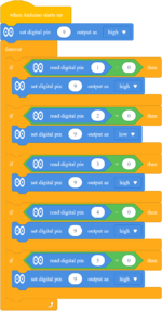
Logic needed:
Buttons should be scanned(endless loop)
initial value of logical output O1 = Steady (latched) high on power on
When button B1 is momentary pressed (0V) , logical output value of O1 = steady(latched) High
When button B2 is momentary pressed (0v) , logical output value of O1 =steady(latched) Low
When button B3 is momentary pressed (0V) , logical output value of O1 = steady(latched) High
When button B4 is momentary pressed (0V) , logical output value of O1 = steady(latched) High
When DI is low (0V), logical output value O1 = steady(latched) High
many thanks in advance!
George
Corrections:
Hello,
Need Mblock example for Arduino Nano board according to the below:
I have 4 momentary push buttons B1-B4 (momentary keyboard buttons) and one digital output DI which I need to code to one latched output O1 to values according to:
so the inputs are B1-B4 and DI (from a sensor with digital output), output is O1 (from a logic sensor). to the Nano board.
All 4 momentary push buttons are pulled up to +5V via resistors: when pressed, logical output is 0V, when not pressed +5V
Logic needed:
Buttons should be scanned(endless loop)
initial value of logical output O1 = Steady (latched) high on power on
When button B1 is momentary pressed (0V) , logical output value of O1 = steady(latched) High
When button B2 is momentary pressed (0v) , logical output value of O1 =steady(latched) Low
When button B3 is momentary pressed (0V) , logical output value of O1 = steady(latched) High
When button B4 is momentary pressed (0V) , logical output value of O1 = steady(latched) High
When DI is low (0V), logical output value O1 = steady(latched) High
many thanks in advance!
George
Need Mblock example for Arduino Nano board according to the below:
I have 4 momentary push buttons B1-B4 (momentary keyboard buttons) and one digital output DI which I need to code to one latched output O1 to values according to:
so the inputs are B1-B4 and DI, output is O1 (from a logic sensor). to the Nano board.
All 4 momentary push buttons are pulled up to +5V via resistors: when pressed, logical output is 0V, when not pressed +5V
Logic needed:
Buttons should be scanned(endless loop)
initial value of logical output O1 = Steady (latched) high on power on
When button B1 is momentary pressed (0V) , logical output value of O1 = steady(latched) High
When button B2 is momentary pressed (0v) , logical output value of O1 =steady(latched) Low
When button B3 is momentary pressed (0V) , logical output value of O1 = steady(latched) High
When button B4 is momentary pressed (0V) , logical output value of O1 = steady(latched) High
When DI is low (0V), logical output value O1 = steady(latched) High
many thanks in advance!
George
--- Updated ---
Corrections:
Hello,
Need Mblock example for Arduino Nano board according to the below:
I have 4 momentary push buttons B1-B4 (momentary keyboard buttons) and one digital output DI which I need to code to one latched output O1 to values according to:
so the inputs are B1-B4 and DI (from a sensor with digital output), output is O1 (from a logic sensor). to the Nano board.
All 4 momentary push buttons are pulled up to +5V via resistors: when pressed, logical output is 0V, when not pressed +5V
Logic needed:
Buttons should be scanned(endless loop)
initial value of logical output O1 = Steady (latched) high on power on
When button B1 is momentary pressed (0V) , logical output value of O1 = steady(latched) High
When button B2 is momentary pressed (0v) , logical output value of O1 =steady(latched) Low
When button B3 is momentary pressed (0V) , logical output value of O1 = steady(latched) High
When button B4 is momentary pressed (0V) , logical output value of O1 = steady(latched) High
When DI is low (0V), logical output value O1 = steady(latched) High
many thanks in advance!
George
Last edited: